Faculty of Engineering & Applied Science
ENGR 4950U - Capstone II Winter 2022
Design & Development of an Autonomous Indoor Disinfection Robot for the Prevention of Airborne Diseases
Course Instructor: Dr. Remon Pop-Iliev
Capstone Supervisor: Dr. Ahmad Barari
Group #: G-19-1-6
Submission Date: Friday, April 8th, 2022
|
Group Members |
|
|
Name |
Student Number |
|
Anas Mohmand |
100620253 |
|
Joshua Piansay |
100668478 |
|
Troy Radam |
100623772 |
|
Johnny To |
100673010 |
|
Tommy Tran |
100655910 |
|
Victoria Uchida |
100657156 |
As healthcare professionals continue to operate and protect themselves during the COVID-19 pandemic, constant disinfection practices and solutions for producing clean air are needed to prevent further exposure and maintain a safer work environment. The ongoing pandemic has created the need for fully autonomous robots, capable of performing surface and airborne disinfection. The deployment of fully autonomous disinfection machines eliminates the worker from performing disinfection practices in possible high risk areas, and aids the need for social distancing. The purpose of this paper is to propose the design and development of an Autonomous IOT-Enabled Disinfection Robot for the prevention of airborne diseases. The robot is to provide efficient and constant disinfection of the air in an indoor environment, be fully autonomous, equipped with obstacle avoidance, and to have strategic path-planning. A number of analyses and testings were conducted to properly evaluate each of the concepts created. Solidworks was used to 3D model, conduct FEM analyses and to simulate the air flow inside each design.
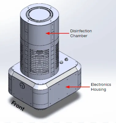
The final design presented in this paper is an autonomous disinfection robot that utilizes UVC and HEPA disinfection and VSLAM technology to navigate through its surroundings. The robot has two compartments: an upper disinfection unit and a lower electronic housing. The disinfection strategy in this design is a maze chamber that aims to extend the exposure time for disinfecting harmful airborne particles. Air is essentially taken from the bottom and passed through an air-tight cylindrical HEPA, through the maze and out of the exhaust. There are two UVC modules: the first one inside the HEPA filter and the second one inside the maze. The purpose of the first UVC module is to inactivate the harmful particles trapped within the HEPA filter. The purpose of the second UVC module is that if a COVID-19 particle were to pass the first UVC module, the second UVC module ensures inactivation of the particle by exposing the air to UVC for a set amount of time. To attain fully autonomous functionality, an embedded PC software known as ROS localizes the robot by using V-SLAM, and controls the robot by sending motor controls. With its fully autonomous function and need to operate for a long period of time, the robot has fully self charging capabilities and its own charging station.
TABLE OF CONTENTS
2.0 DESIGN PROBLEM DEFINITION & OBJECTIVES 5
2.3 Problem Definition Statement 7
2.4 Criteria Success and Project Objectives 8
3.0 PRELIMINARY DESIGN PROCESS AND DOCUMENTATION 9
3.4 Test, Verification & Implementation of the Solution 14
3.5 Preliminary Detailed Design Documentation 17
3.5.1 Disinfection Unit Design 17
3.5.3 Autonomous Navigation 22
4.1 Feedback Received from Project Stakeholders 24
4.2 Design Changes and Enhancements 25
5.0 FINAL DESIGN DOCUMENTATION 30
5.1 Disinfection Unit Design 30
7.2 Sensors and Actuators Testing 40
7.2.2 Air Quality Sensor Test 42
10.0 ETHICAL CONSIDERATIONS 49
Appendix C - Prototyping Process 70
Appendix D - Failure Modes & Effects Analysis (FMEA) 75
Appendix E - Product Manual 78
The initial scope of this project is to design and develop an autonomous indoor disinfection robot for the prevention of airborne diseases. With the increasing concern for airborne contagion through the COVID-19 pandemic, this project’s intent is to deliver an intelligent and efficient solution to combat the ongoing problem. The robot’s main features can be summed down to the following: disinfection process, autonomous navigation with obstacle avoidance, and strategic path-planning. The disinfection is a two-stage process; It begins with intaking air that will be filtered through a High-Efficiency Particulate Air (HEPA) filter which is subsequently passed through Ultraviolet-C (UVC) lights. Paired with these two mechanisms, strong evidence suggests efficient bioaerosol disinfection due to the inactivation of RNA replication in such organisms [1]. The autonomous navigation portion involves designing a robot that possesses the ability to perceive the surrounding environment and execute decisions based on the objective of disinfection. The intent of integrating autonomous functionality and path-planning to the design of the robot is to minimize the need for individuals to conduct work in a contaminated area and improve the efficacy of the disinfection. This can be achieved by having the robot remain in a contaminated area until the recommended amount of disinfection has taken place. Likewise, the robot should be able to sense human activity and prioritize disinfection where social distancing cannot be avoided.
Using existing solutions of the autonomous disinfection robot market, a better understanding of the current state of the art can be obtained. There are a variety of disinfection solutions used by different products such as external UVC disinfection, UVC disinfection through air exchange, chemical disinfection, and a combination of these solutions. With the type of disinfection selected, multiple components and features including an autonomous feedback mapping system are paired to allow the robot to fully navigate through different environments and to ensure overall safety during disinfection.
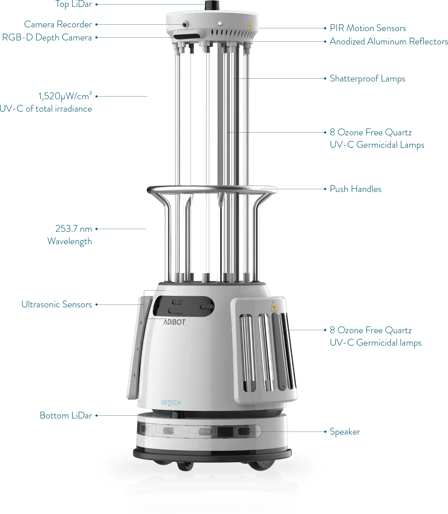
The idea of external UVC disinfection can be described by placing UVC lamps on the outside to disinfect the surrounding air. There are many configurations that can be used with external UVC disinfection but most common are when the lamps have a 360° radiance as seen in Appendix A. Figure A-1 is an external UVC autonomous disinfection robot called ADIBOT-A which was created by UBTECH, an AI and humanoid robotics company [2]. It is a fully functional disinfection robot that can be programmed and mapped to navigate different environments such as schools, hospitals and offices. This existing robot also includes smart control, U-SLAM mapping technology and many safety features.
The idea of internal air-exchange UVC disinfection solutions can be described by directing air to pass through the UVC lamps. Current air-exchange solutions have the UV-C lamps blocked in a way to prevent UVC radiation. Figure A-2 is another existing UVC disinfection solution called UltraBot. However, instead of the UVC having a 360° radiance, it is equipped with a UVC blocking shield used to create a disinfection area of 180° and allow a safety zone for people to safely pass through during disinfection. It is also fully equipped with autonomous and safety features to help navigate through areas.
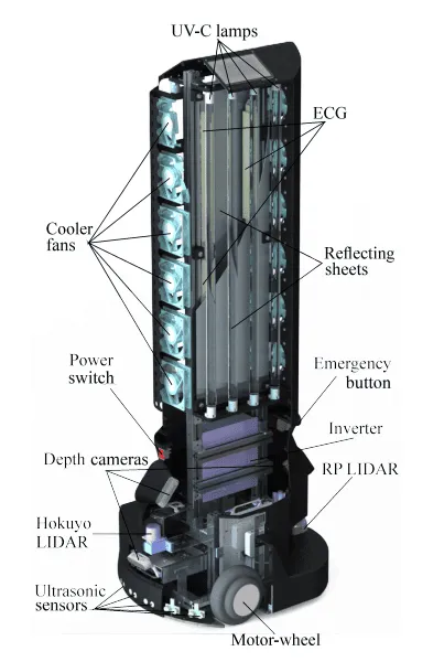
The smart cleaner is an autonomous indoor disinfection robot designed to combat the COVID-19 pandemic [3]. The smart cleaner uses a chemical approach to disinfection. Figure A-3 makes use of an ultrasonic atomizer module that is mounted at the top of the robot, which is able to convert a hydrogen peroxide liquid solution into a micrometer-sized dry-mist aerosol used for disinfection. For efficient indoor space disinfection, the outlet of the ultrasonic atomizer module was designed to have multiple exiting ports for the dry-mist hydrogen peroxide (DHP) aerosol to flow out and fill the indoor space with the solution. As the DHP solution fills the room, it disinfects the airborne/surface bacteria and pathogens in the area. The robot’s navigation is based on SLAM and Robotic Operating System (ROS), and this is achieved using the RGB depth camera mounted on the front side of the robot, and the LiDAR sensor positioned underneath the disinfection module.
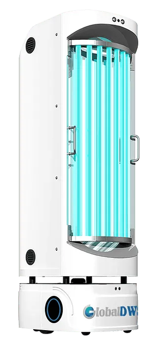
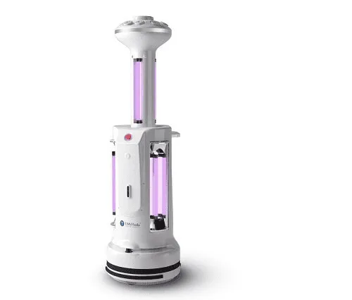
There are a number of robots in the market that employ a combination of multiple disinfection modalities (refer to Figure A-4). The Disinfection Service Robot (DSR) offered by GlobalDWS [4] is another autonomous solution to dealing with airborne and surface-dwelling bacteria and viruses. It is equipped with external UVC light as well as an antiviral disinfectant spray outlet mounted at the top of the robot for a multi-barrier approach to disinfection. The navigation system is based on SLAM and also has human presence detection capabilities. An alternative approach to multimodal disinfection is the Intelligent Disinfection Robot from TMiRob [5]. It uses a combination of external UVC Light, dry-mist hydrogen peroxide, and a HEPA air filtration system with internal UVC light. This autonomous solution offers the capability to switch from a combination of the disinfection modalities depending on the environment.
As with any product on the market, the features should be driven by customer needs. With the ongoing development of the COVID-19 pandemic, solutions to providing clean air in indoor spaces are an emerging market. Companies are beginning to welcome people back into their establishments, which poses risks for both the customers and the staff. Therefore, the solution should provide a safe environment for everyone to cohabit and ensure a sustainable means to controlling the spread of micro-bacteria and other virulent particles that can exist in the air.
The primary customer requirement is that the product should be safe. No product can be successful nor profitable if it cannot be safely used in the environment that it was designed for. Given the fact that the disinfection robot is required to handle indoor spaces, it is bound to come into contact with at least one person. Whichever features are implemented in the final product, it must be able to be used safely around large groups of people.
It is also imperative that the product is able to operate with little to no human intervention. The task of disinfecting a contaminated area would put a person in an area with possible virulent air particulate, therefore, the application of a robot to carry out this task would be suitable. A product that satisfies this customer requirement would be more appealing to the consumer market than one that requires an individual or a team to carry out this task.
Another critical consideration that must be met which is driven by any product on the market is cost. A product that performs well will not be marketable if it costs an exorbitant amount of money. The solution should be reasonably priced in order to compete with existing market solutions and provide a sustainable method to help companies control the spread of COVID-19. The less expensive the final product is the more units that a customer is likely to purchase.
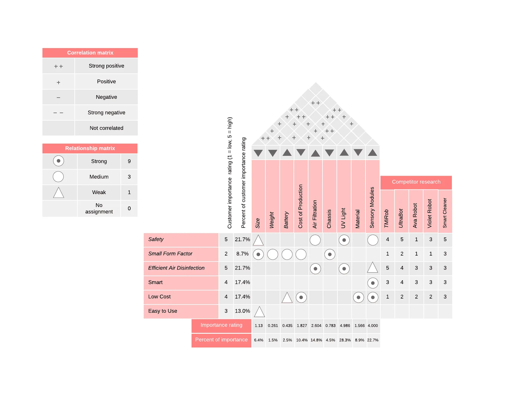
To help translate the customer requirements into comparable engineering specifications, the Quality Function Deployment (QFD) methodology is applied using a House of Quality (HOQ). Referencing the House of Quality (Figure A-5), the product development team is able to quantify the importance of each customer requirement, as well as its importance in relation to the product characteristics. Additionally, the deployment of a HOQ allows the team to gather more information on how well each competitor fares relative to each customer requirement category. This ultimately allows for the team to move towards determining the specific quantitative engineering requirements and goals to aim for when developing the disinfection robot.
In reference to the HOQ (Appendix A), it is clear that the most important factors regarding the disinfection robot product are its ability to operate safely around people in indoor environments, as well as the efficiency of the air disinfection. Following this is the robots’ ability to operate and carry out tasks with little to no human intervention (smart), and the lower the cost of the robot the better. As the different systems of the disinfection robot will be engineered/designed concurrently, it is important to note the correlation matrix between each of the engineering product specifications, This will allow the team to determine which subsystems must be designed in parallel and which teams must be communicating with each other during the design. Using the information from the HOQ, a table of possible engineering requirements and goals was constructed (Table B-1). Additionally, possible system implementations were brainstormed and added to this table as well.
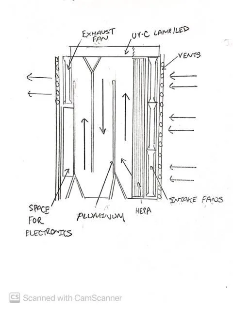
Concept 1: Maze Approach
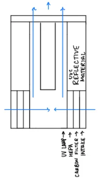
Similar to other designs the maze approach utilizes UVC light and HEPA filters. The fans and HEPA filters are situated at the intake to filter air. There is also an exhaust fan and UVC light along the top. Additionally, this design uses two partitions in the main chamber to divide it into three sections. As shown in Figure A-6, the partitions only go part way to the top of the chamber so the air can flow from section to section. The partitions create a maze-like path for the flow to follow so the air takes longer to reach the exit. This longer travel time allows for more UVC light exposure time. This design also incorporates an aluminum lining to increase UVC reflectivity.
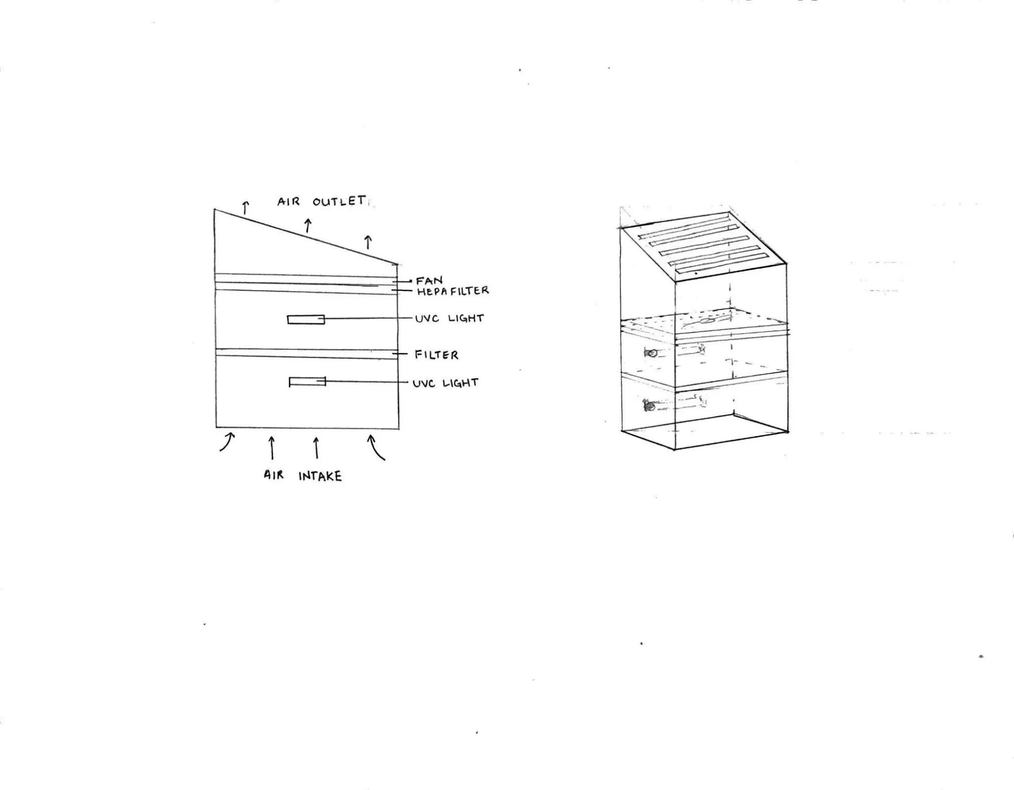
Concept 2: Two-Chamber Approach with UVC
The two-chamber design, displayed in Figure A-7, can operate in private and public spaces as well. The two-chamber design uses filters and UVC light to disinfect the air. The filters and lights are housed inside the body of the robot, to avoid any human exposure to the UVC light. Air is taken in from the bottom, passed through filter 1 and filter 2, and then exhausted. The two filters divide the body of the robot into two chambers, to slow the flow of air through the system to increase UVC exposure time.
Concept 3: Hybrid Design: Airborne & Surface Disinfection
The hybrid design concept displayed in Figure A-8 can operate in both public and private spaces, which feature airborne and surface disinfection, respectively. For clarity, in this paper public spaces will refer to human-occupied spaces whereas private spaces will refer to spaces with no humans present. This dual functionality is possible through sliding panels in the tower housing the UV lamp.
In the public configuration, the sliding panels on the tower will be closed and the UV lamp will not be exposed to the external environment. This will ensure safe public use through the prevention of human exposure to UV light. This configuration will follow our current design approach of dual disinfection through a HEPA filter and internal UV light. Air will enter the box through the intake fans, pass through the HEPA filter, travel to the tower where UV disinfection will occur, and finally exit via the exhaust fan.
In the private configuration, the sliding panels on the tower will be open and the UV lamp will be exposed to the external environment. Since the UV lamp is exposed, this configuration would only be used in private spaces for tasks such as disinfecting a hospital room in between patients. This configuration would feature only UV disinfection, and the air filtration module (intake/exhaust fans and HEPA filter) would be disabled. This is because UV disinfection is already very effective in both airborne and surface disinfection, and thus a second disinfection method may become redundant.
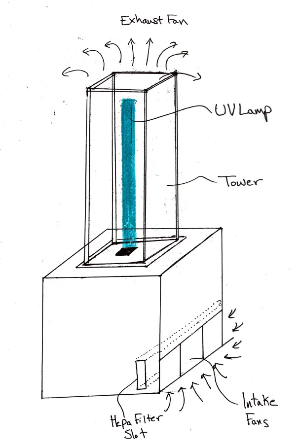
Concept 4: UV Disinfection with Bladeless Impeller approach
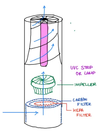
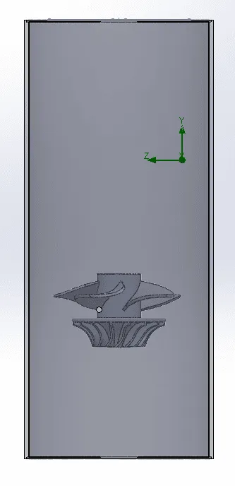
Another UVC disinfection design concept displayed in Figure A-9 can also operate in environments where humans or no humans are present. This can be done by using UVC reflective material such as aluminum as an inner liner to maximize the effectiveness of the UVC exposure to the air inside the machine while also limiting the UVC to humans. This design approach uses cylindrical filter cartridges for both the Carbon and HEPA which can be inserted by removing the top part of the proposed design. Air is taken through the bottom side of the cylinder, through both filters, and into the bladeless impeller where it is then passed through a UVC light, exhausting out clean air. The use of a bladeless impeller allows for less noise than a traditional tower fan and can potentially intake and exhaust more volume.
Concept 5: Ionizer and Surface Cleaner Approach
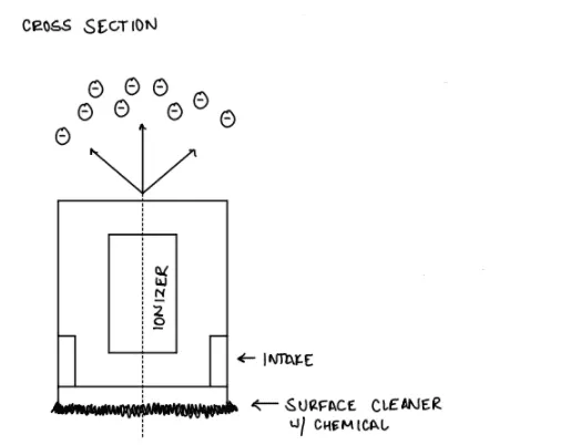
The ionizer and surface cleaner design, displayed in Figure A-10 is another hybrid disinfection approach that can only operate in a private environment. This concept uses an ionizer and surface cleaning combination, where the ionizer releases negatively charged ions into the air where it bonds with the positive air particulate ions in the room. The bonded ions then fall onto the ground ultimately disinfecting the air in the room. However since the airborne particulates are now on the floor, the surface cleaner is used to clean the floor. This approach is ideal for private configuration because like a caretaker mopping the floor, the surface has to dry before any occupants can enter the room. Moreover, the environment needs to be completely empty of both humans and furniture as this design concept has no way of cleaning elevated surfaces such as tables, chairs, and desks.
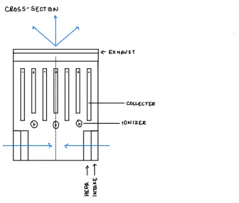
Concept 6: Ionizer with Collector Approach
The ionizer equipped with a collector design, displayed in Figure A-11, is similar to the previous ionizer concept, except that the ionizer releases negative charged ions inside the machine rather than out into the air. Air is taken from the bottom where it is passed through a HEPA filter and then bonded with the negative charged ions. The collector inside the machine then collects the bonded ions, allowing for clean air to be exhausted. However, unlike UVC, the harmful airborne particles are not yet destroyed and the collector must be cleaned regularly.
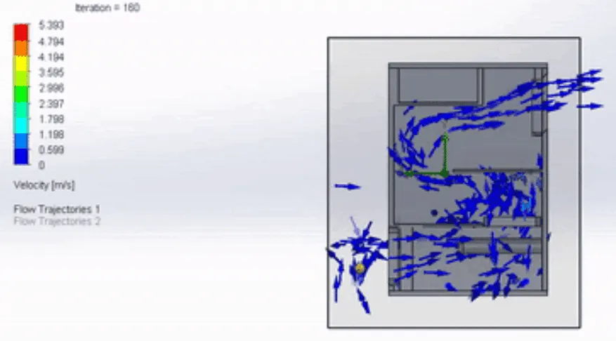
From the concepts proposed in Section 3.1, concepts 1, 2 and 4 showed the most potential, and were advanced to the next phase of the design process. Flow simulations were conducted on these concepts to further our understanding of their advantages and limitations. Primarily, we were looking to see which designs would be the most effective in increasing the travel time of the particles, to increase UVC exposure time.
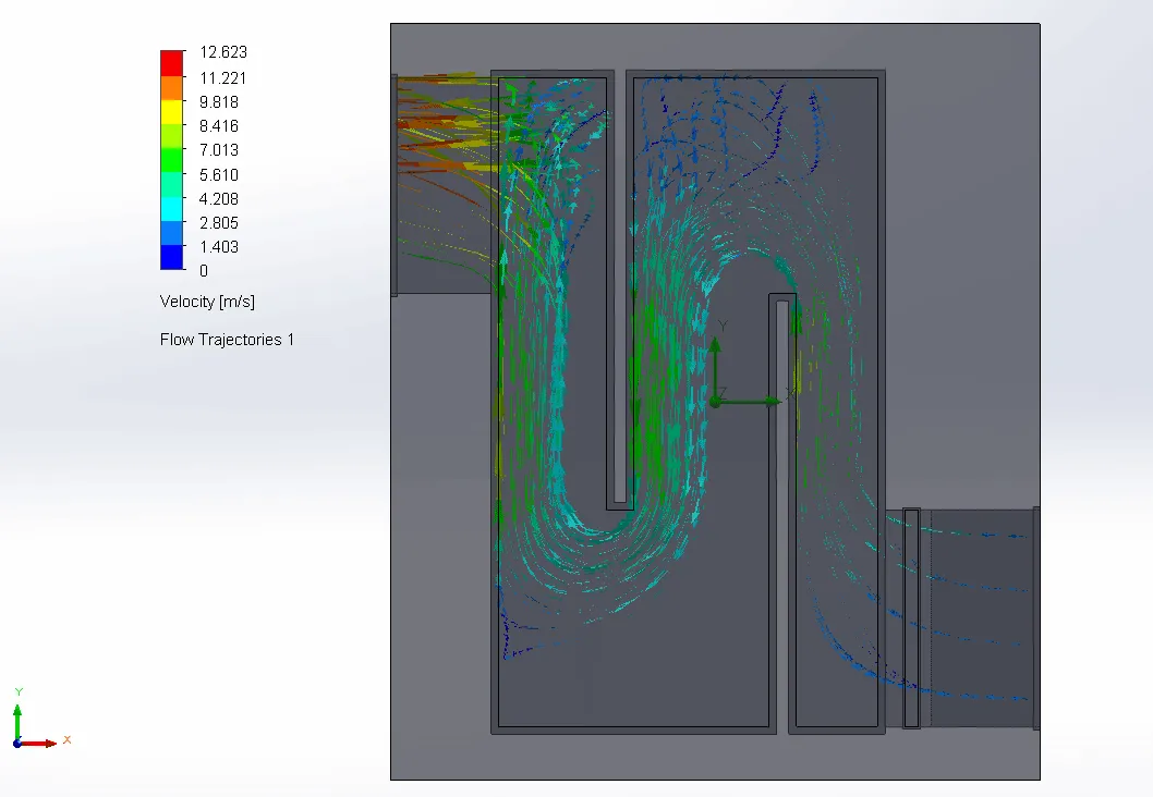
First, the flow simulation for concept 1 was performed, which is displayed in Figure 1. The simulation proved the effectiveness of the maze in increasing the travel time of the particles. It also showed us that there were empty spaces in the corners where no flow was travelling. This led us to conclude that the corners should be rounded to promote flow, and that the dimensions of the maze should be reduced to avoid the areas of no flow.
Figure 1. [Concept 1] - Flow Simulation
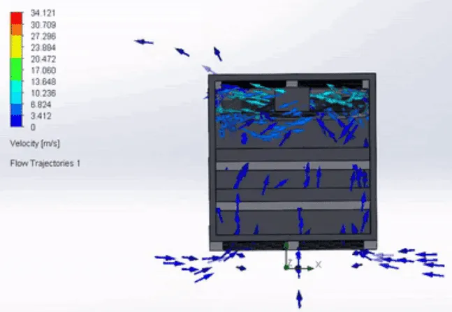
Figure 2. [Concept 2] - Flow Simulation
Next, the flow simulation for concept 2 displayed in Figure 2, proved that the flow can be severely impeded by the placement of the filters, and then speed up as it exits through the exhaust. However, multiple filters for the sake of impeding the flow seemed to not be the best approach as the second filter was redundant.
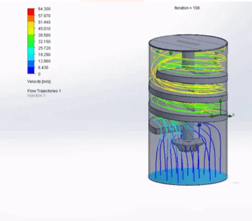
Finally, the flow simulation for concept 4 proved that a spiral would be a top choice for increasing the travel time of the particles. The spiral is clearly efficient and does not have any areas of no flow.
Figure 3. [Concept 3] - Flow Simulation
The concepts discussed in section 2.1 were evaluated in a concept selection matrix based on the engineering targets set in section 1.4. This matrix is available in Table B-2. The top 3 concepts were the Maze (+6), Bladeless Impeller (+5), and the Two-Chamber (+4). These three concepts more or less incorporated the same design; airborne disinfection via HEPA filter and internal UVC. However, the Maze concept scored the highest as it met all engineering targets. Specifically, it met the top four important criteria established in Section 1.4 (sensors, manufacturability, UV light, and air filtration). The sensors used are essentially the same in each concept as the final design requires autonomous navigation capabilities. The box shape of this design allows the addition of all sensors with ease due to its ability to be easily partitioned and manipulated. Also, the uniformity of the box allows easy access to all sensors as required. In regards to manufacturability, the base design would consist of a hollow box with cutouts to house all sensors, fans, and more. This design can be 3D printed as several modular pieces and then installed. With respect to the UV light criteria, the design consists of UV lamps inside the box. As the maze will impede the flow, the UV lamps will be strategically placed to maximize particle exposure time for disinfection. Finally, this concept achieves the air filtration target via a HEPA filter, intake, and exhaust fans.
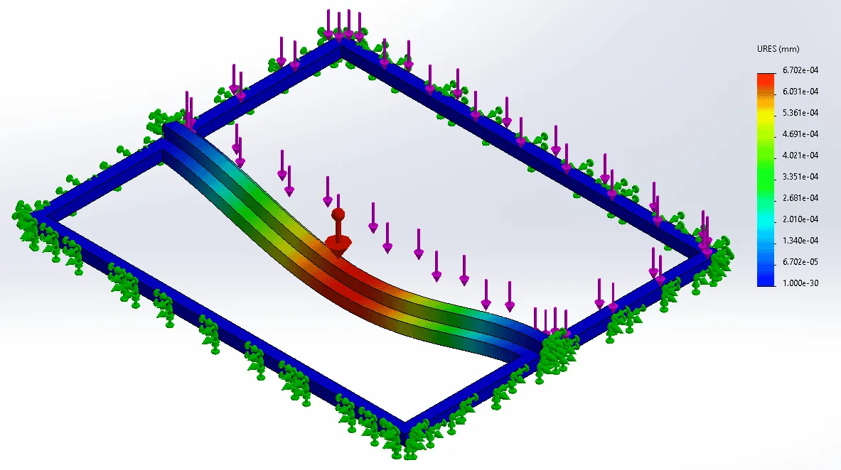
Baffle Bracket
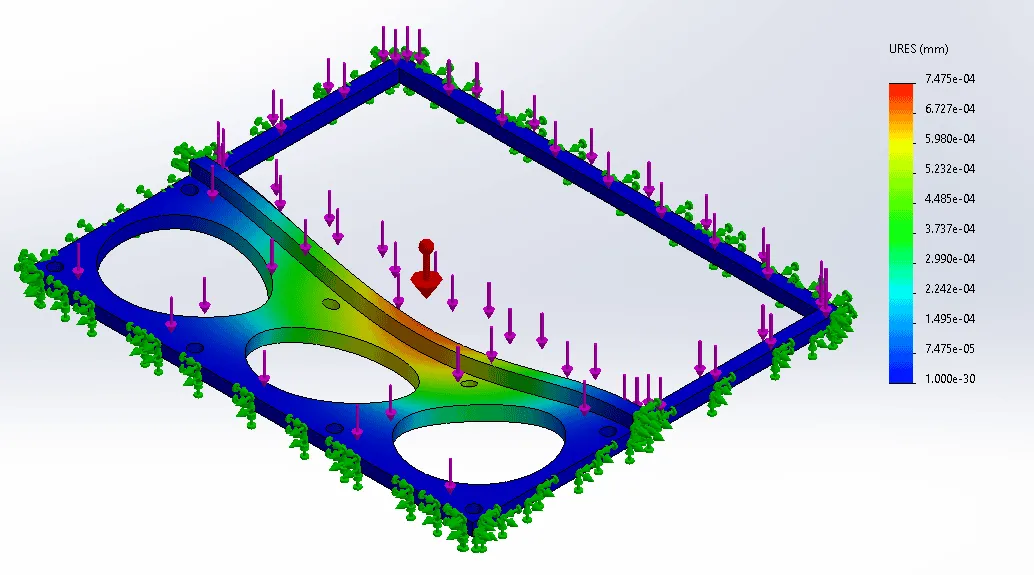
Quartz-glass baffles are used to maximize the dwell time of air inside the disinfection chamber without suffering any major loss of UVC exposure. In order to properly secure the baffles inside the chassis of the disinfection chamber, two non-standard brackets were 3D-modeled and analyzed with FEM (Finite Element Methods) through SolidWorks 2021. The lower bracket would be used to mount the first three 120mm high airflow fans and the quartz glass and the upper bracket would be used to mount the quartz glass alone. An FEA (Finite Element Analysis) was conducted to simulate the stresses being applied to both brackets and to determine any type of displacement. It is assumed that the brackets and the inner wall are the same material and come as one piece, therefore no external reinforcement is currently needed. A force of 2.479 N was placed down along the baffle side and a force of 3.1458 N was placed down along the fan module side. From the results, it was noted that the maximum displacement acting on the lower baffle bracket and upper baffle bracket were 0.0007475 mm and 0.0006702 mm, respectively. Overall, the brackets yielded positive results, acceptable to use as a final housing bracket for the quartz glass and fans.
Figure 4. Displacement Graph of Fan Module and Quartz Glass acting on the Lower bracket.
Figure 5. Displacement Graph of only Quartz Glass acting on the Upper bracket
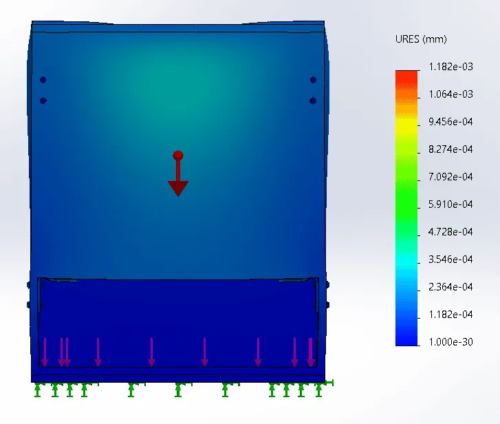
Disinfection Module Housing
Figure 6 displays the displacement graph for the disinfection module housing. The UVC lights, fans, and quartz baffles will all be housed in or on this part. This part will be made out of an aluminum alloy, for this test a 7079 aluminum alloy was used. The housing was subject to the force of gravity and a force of 4 newtons along the frame to simulate their weight. From the simulation, the maximum displacement of the part was found to be 0.001182 mm. From this result, the housing was deemed acceptable for use.
Figure 6. Displacement Graph of Disinfection Module Housing
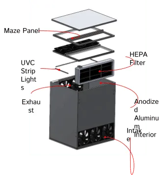
The final design chosen for the disinfection unit was a refinement of concept 1, the maze design. The specific components implemented in this unit are displayed in Figure 7.
Figure 7. Final Maze Design (Exploded View)
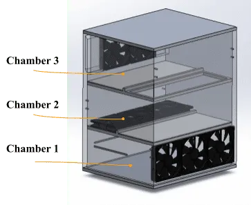
The unit is divided into three chambers, as shown in Figure 8. In the first chamber, air is drawn into the system via 3 intake fans, and pushed through the filtration system. UVC strip lights are mounted on the walls opposite and adjacent to the filtration system, providing surface disinfection of the filter. This is to ensure that the particles caught in the filter are permanently eradicated and have no chance of leaving the filter. The second chamber acts as a factor of safety, in the event an infected particle makes it through the filter. Air is drawn into the second chamber via 3 fans. UVC strip lights are mounted on the walls of this chamber, providing airborne disinfection of all particles passing through. Baffles are organized in this chamber to impede the flow and extend the residence time of the particles to maximize exposure to the UVC disinfection. Finally, the third chamber consists of the exhaust system, where two fans push clean air out of the system and into the environment.
Figure 8. Final Maze Design (Interior View)
A flow simulation of the final design, displayed in Figure 9, was performed and yielded the expected results. The air travels into the system through the first chamber and is restricted from flowing directly out of the exhaust by the baffle located in the second chamber. The travel time is successfully extended and leaves through the exhaust. The fans located at the beginning of the second chamber successfully provide the interface between the first and second chambers. The filtration system causes a reduction in the speed of the particles, and therefore it becomes necessary to introduce a vessel to promote the airflow into the maze/second chamber.
Figure 9. Final Maze Design (Flow Simulation)
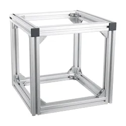
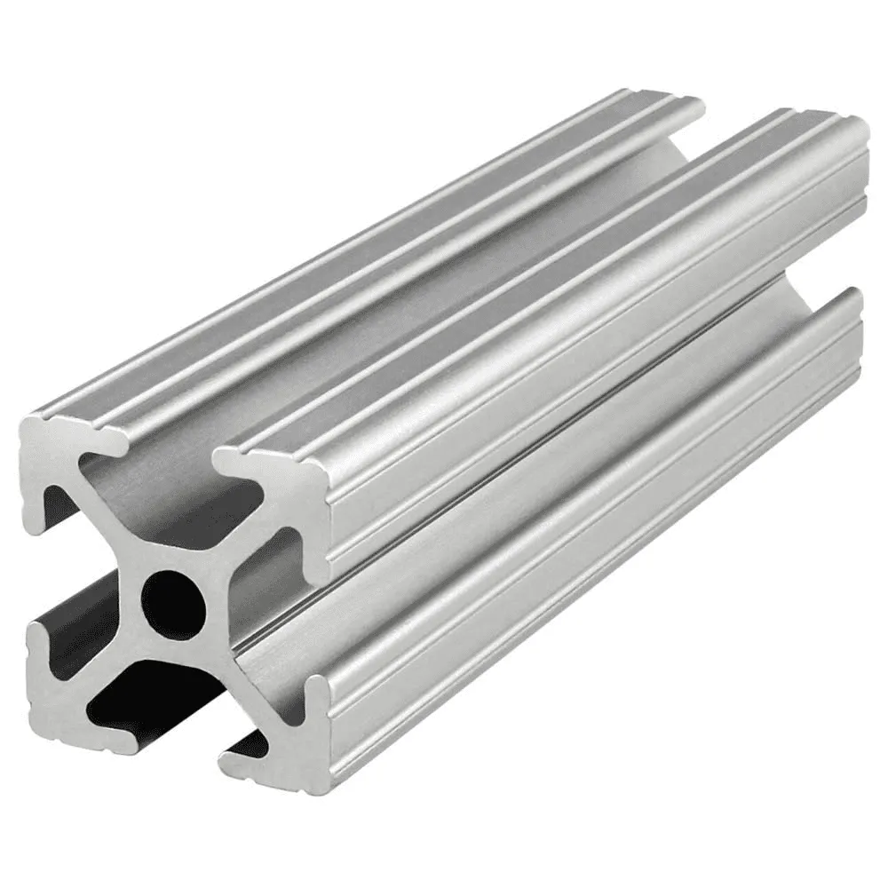
The main frame of the disinfection unit will be constructed using aluminum extrusion. As displayed in Figure 10, aluminum extrusion is effective in providing a rigid structure. Several bracket options exist for connecting aluminum extrusion. We will be using corner brackets to connect the extrusions, as displayed in Figure 10. Extrusion is very commonly used in industry, thus proving to be an effective and reliable solution.
Figure 10. Aluminum Extrusion and Corner Brackets
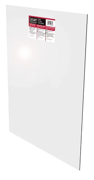
Polycarbonate sheets (see Figure 11) will be slid into the extrusion guide rail (see Figure 11), to cover the sides of the unit. Non-transparent polycarbonate sheets will be used to ensure the UVC light is not exposed. Polycarbonate is an inexpensive and effective solution.
Figure 11. Polycarbonate Sheet (left), Extrusion (right)
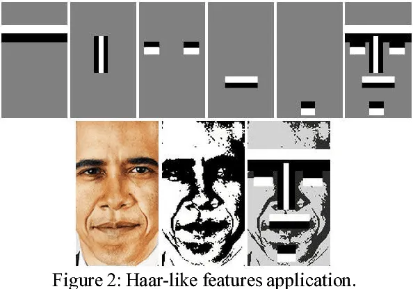
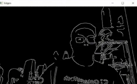
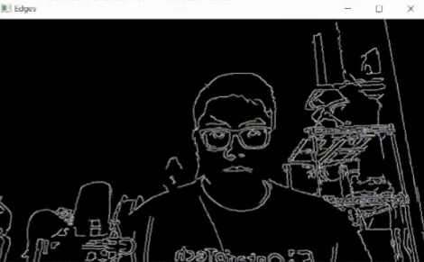
There is the need for the robot to be able to determine the number of people that are in its vicinity. This serves two purposes: keeping track of the current number of people in the room to gauge how long it needs to disinfect that area, and also to be able to interpret this data so that the next decision can be made as to where the robot will go next. Currently, the preliminary work involves the use of the Logitech C920 3MP 1080P HD USB mono camera with a diagonal field of view of 78 degrees. This camera is used for face detection using pre-trained haar cascade models with openCV classifiers. The premise of this technology is that there are particular features that the camera can distinguish, which in this particular case are called haar features. Shown in Figure 12 below, the algorithm requires that these distinct light and dark haar features are utilized to train the classifier. The first image on the left with the horizontal white and black bars are supposed to represent the brow of the face. The transition between the light and dark is something that the camera is capable of detecting. Likewise, the single white vertical line bounded by two black lines is the haar feature for the bridge of a nose. These distinct individual features are brought together to train the classifier so that it can analyze the pixels involved in the object.
Figure 12. Haar features derived from distinct areas on the face [6]
The cascade of classifiers is an approach to mitigate the amount of error in this process. The first step was to recognize that the majority of the image does not involve the face. The area that the face actually takes up on the image takes up a small fraction compared to everything else in the image. There are thousands of features that the camera can look for, but it would take too long to process anything tangible if it were to scan every pixel for certain haar features. Instead, the features are grouped together into different stages of classifiers that check sequentially. This means that if a certain area does not pass the first stage of the classifier, that region is disregarded and not checked for the remaining features.
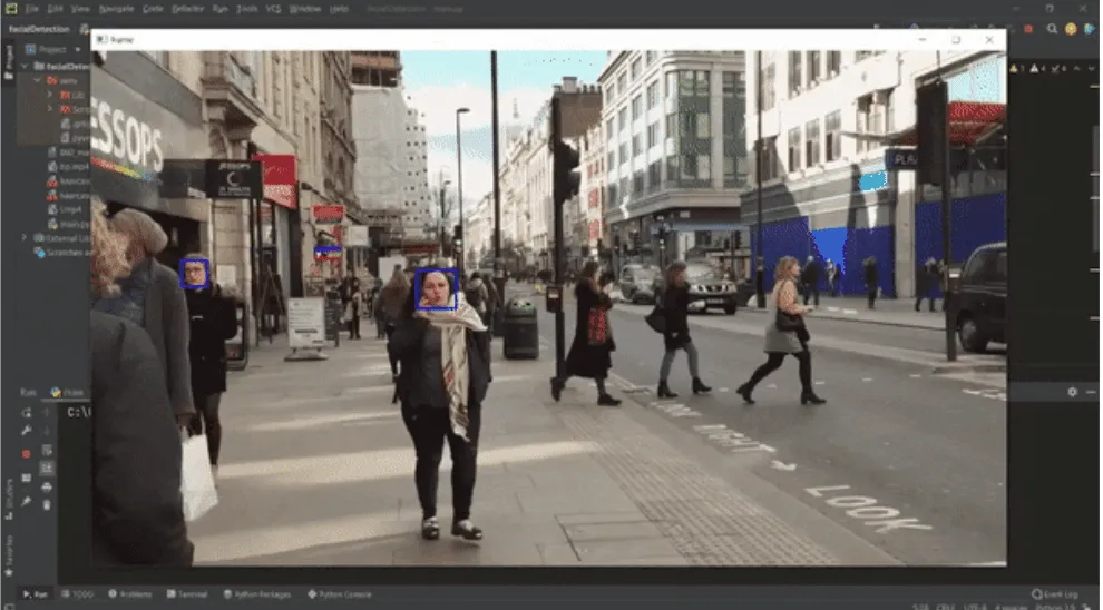
Figure 13. Preliminary face detection algorithm overlay on recorded video
Currently, the system is not tuned enough yet to detect faces accurately and rapidly. There is more work required to develop the accuracy and repeatability of the algorithm against varying backgrounds and distinct facial features. One area of potential improvement would be to implement body detection so that the algorithm can predict where the face will be quicker. A simple approach to this would be that the haar features used to distinguish a face would always typically be on top of the body feature. It was found that applying Gaussian blur to these images resulted in less noise. As a result, the detection rate was significantly improvedgtfh
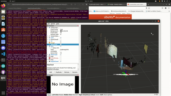
In order to achieve both effective disinfection and efficient autonomous navigation, Robot Operating System (ROS), will be implemented in the embedded PC of the robot. The system is utilizing the NVIDIA Jetson Nano with ARM Cortex-A57 CPU with a Maxwell GPU. ROS will serve as the framework for the software architecture and development and will also be the central point of communication across the different devices. In order for the robot to navigate autonomously, a map needs to be created for the robot to use during operation. Visual simultaneous localization and mapping (V-SLAM) is a process which determines the position and orientation of the robot with respect to its surroundings, while simultaneously mapping the environment around the sensor obtaining that data. Thereafter, ROS will interpret the information gained from the map and send motor commands accordingly to the microcontroller unit to move the robot.
Figure 14. SLAM driven by Intel Realsense L515 using RTABMAP packages for localization
The team is currently utilizing an Intel Realsense L515 2D lidar camera which is the sensor responsible for collecting the data for SLAM, as shown in Figure 14. Although the majority of the mapping algorithm will be handled by packages that come with RTABMAP, a lidar-SLAM-based algorithm, localization information must still be fed into the algorithm. The pose of the robot is achieved by Dead Reckoning, which is a process of calculating the current position of the robot by using its previous position, speed, direction, and elapsed time. It is able to determine all this information from the encoder data from the VEX 775 Pro motors that drive the robot, which will allow odometry information of the robot to be calculated. There is an onboard inertial measurement unit (IMU) inside the L515 that is used to compensate for errors from Dead Reckoning. The encoder data are relative measurements and the error is therefore unbounded which means that it will compound so long as the system is running. By using Dead Reckoning, the IMU inside the L515, and visual localization from the Intel Realsense camera, the robot will be properly localized in the map created from RTABMAP, achieving autonomous navigation using the navigation stack available to ROS.
From the project stakeholders, we received feedback regarding the aesthetics of the robot. First, it was suggested that the robot be more aesthetically pleasing, by incorporating softer edges and curves. At that stage, the robot appeared very boxy with sharp edges. Stakeholders suggested the use of plastic due to its relatively lower cost, weight, and malleability. Combining plastics with manufacturing processes such as 3D printing would allow for a higher degree of customization, thereby helping to improve the aesthetics.
Next, it was suggested that the robot should be as light as possible, and to reevaluate the material choices. At that stage, the material to be used for the large majority of the robot was metal and acrylic. Removing the unnecessary weight caused by those material choices would help reduce the stress on the motors, save energy, and thus extend the operational time of the robot between recharging and maintenance. Plastic was also recommended for this use.
Moreover, to help determine which type of fan and fan configuration to use, it was suggested to conduct tests on the theorized configurations to determine which performed best. At the time, a few different options were being considered. To determine the optimal configuration, it was advised that each fan be tested on its ability to pull or push through the filter.
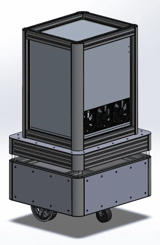
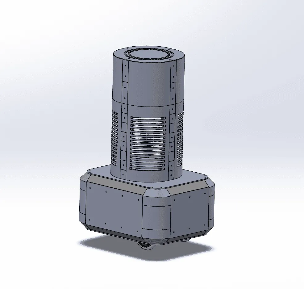
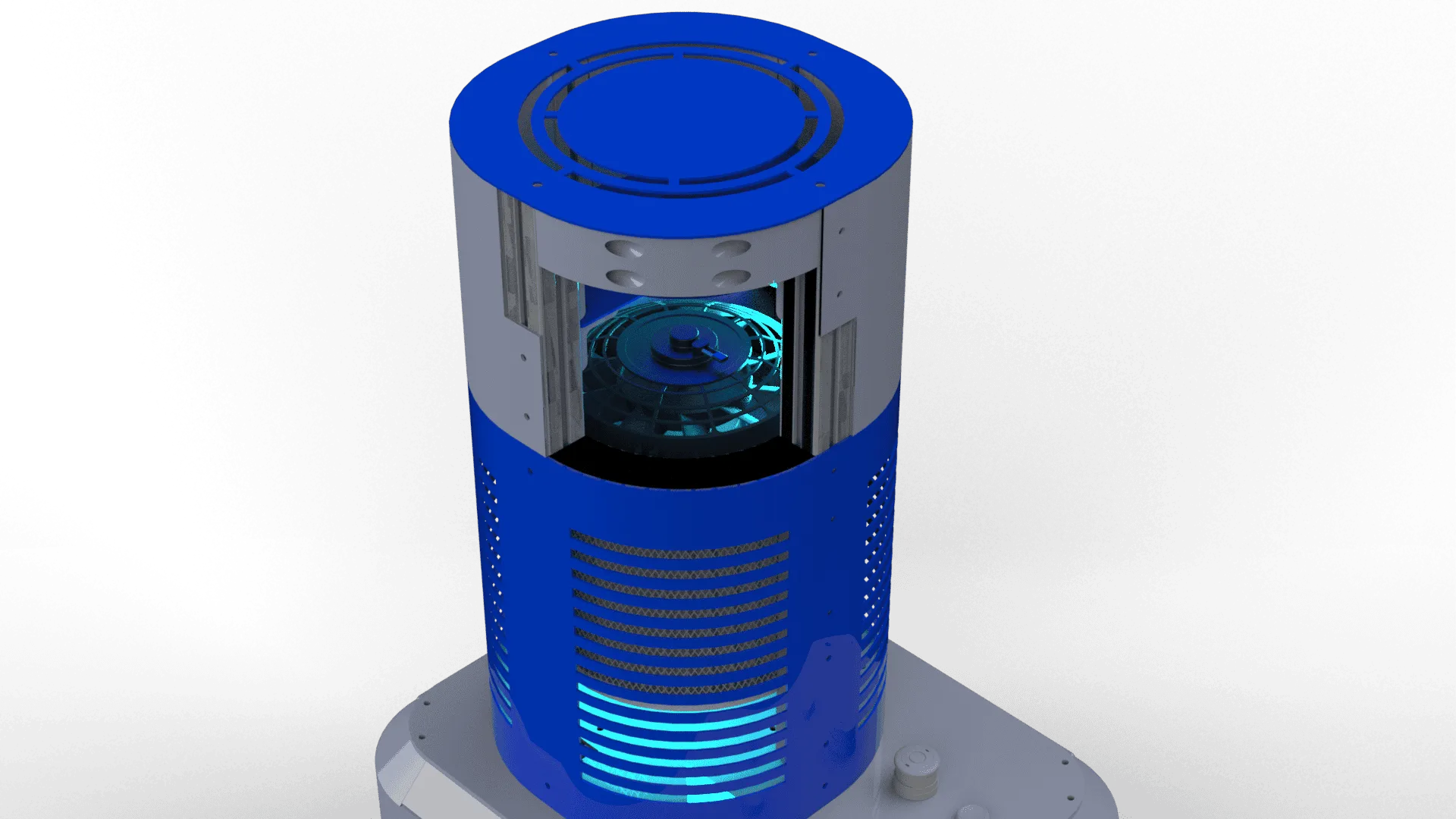
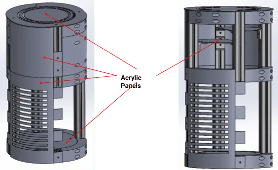
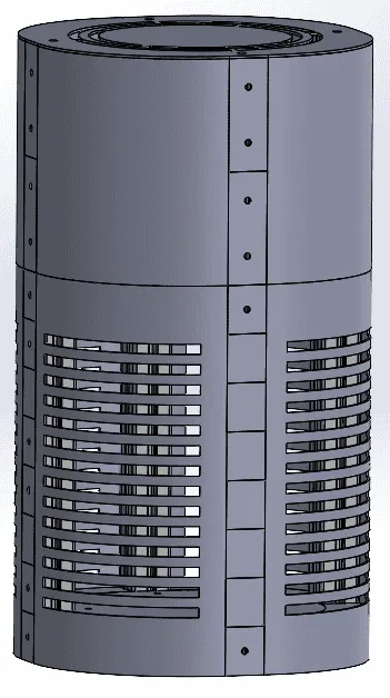
Based on the feedback received, design changes were made accordingly. A comparison of the old and new designs are displayed in Figures 15 and 16. The new design featured several improvements in functionality, aesthetics, accessibility, and more.
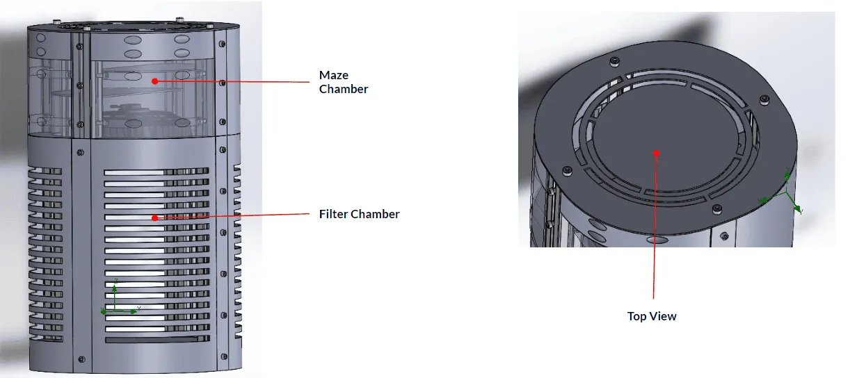
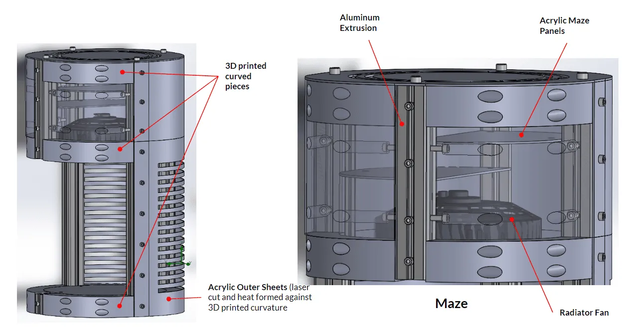
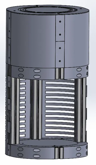
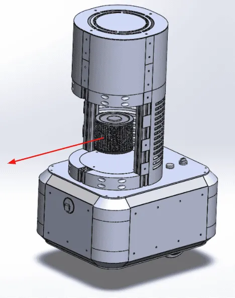
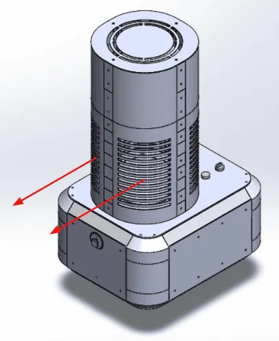
The new filtration system, displayed in Figure 17, consists of the same chambers as the previous design. Namely, these two chambers are the filter chamber and the maze chamber. A cylindrical HEPA filter mounts inside the filter chamber, which serves as the primary mode of disinfection. The maze chamber has now been converted to a spiral path to accommodate the new circular shape. This will help extend the particle’s exposure to airborne disinfection - performed by UVC germicidal LEDs located along the inner circumference of the maze chamber. These two chambers are tied together with a 12V electric radiator fan. Finally, the purified air leaves through the vents at the top of the maze chamber.
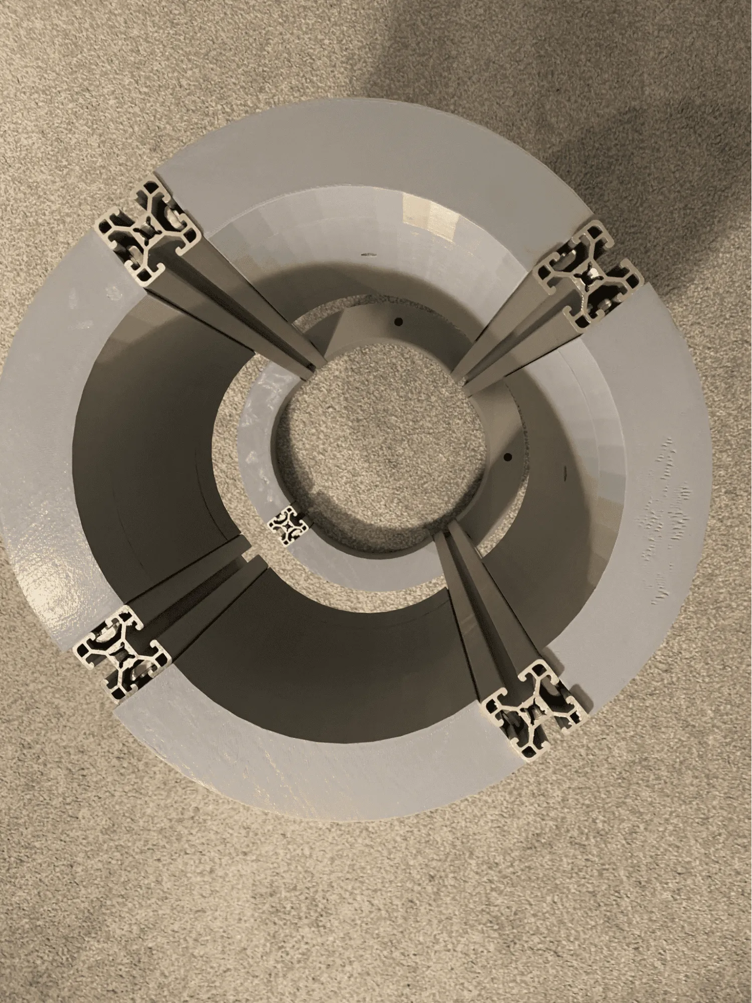
The specific components of the filtration system are displayed in Figure 18. We decided aluminum extrusion was still the best option for a rigid frame. To incorporate different manufacturing processes and improve the aesthetic as requested by the stakeholders, 3D printing is to be used to develop the curved pieces in this design. The curved pieces connect to the extrusion, forming the frame of the cylindrical shape. Heat-formed acrylic sheets take on the shape of the frame to enclose the internal chambers. The acrylic panels are to be laser cut and would also be used for the maze panels.
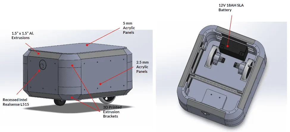
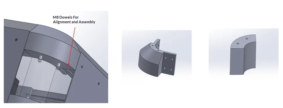
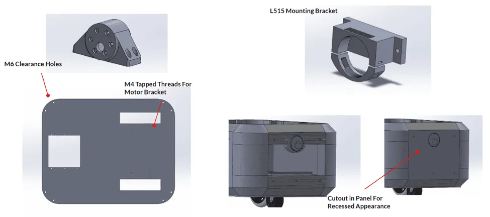
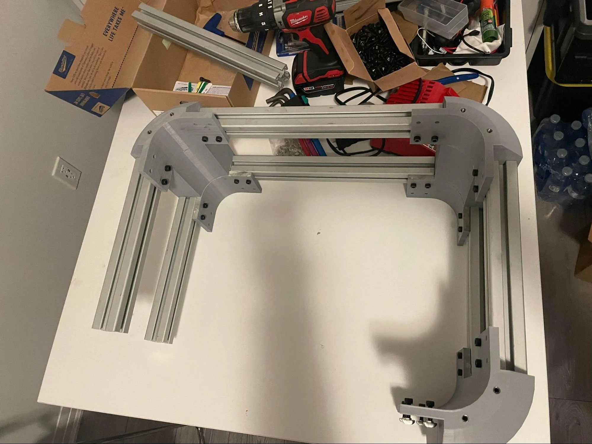
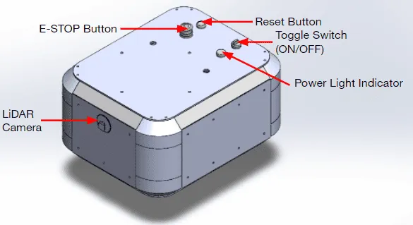
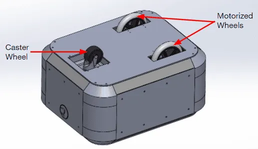
Similar to the filtration portion of the assembly, the bottom chassis would still utilize some aluminum extrusion for the frame, incorporating 3D printed pieces and acrylic as well. As displayed in Figure 19 the refined design has rounded corners, achieved by 3D printing support pieces, and fewer sharp corners, achieved by using angled aluminum extrusion pieces. The 3D printed corner pieces, displayed in Figure 20, are assembled using M8 dowels. Acrylic panels attach to the aluminum extrusion, and the acrylic for the top panel is to be thicker to support the weight of the filtration system. Finally, as shown in Figure 21, there will be an acrylic panel with a cut-out for the LIDAR. This allows the LIDAR sensor to sit recessed in the base of the robot, to protect it and add to the aesthetic appeal.
Figure 15 - Preliminary design from original concept
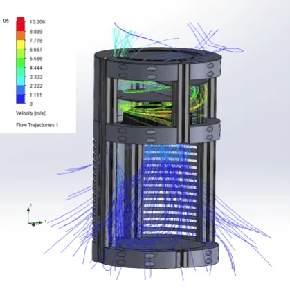
A flow simulation was conducted to plot the trajectory of the flow. The study yielded desirable results as displayed in Figure 22. The fan pulls in air through the filter chamber and passes it into the maze chamber, where the path is successfully extended and finally the clean air exits the system through the top.
Figure 16: Revised Design
Figure 17: Filtration Assembly Chambers
Figure 18: Filtration Assembly Components
Figure 19: Bottom Assembly
Figure 20: Bottom Assembly - Corner Brackets
Figure 21: Bottom Assembly - Component Mounting
Figure 22: Flow Simulation
As mentioned, the new cylindrical disinfection unit shares the previous design’s disinfection strategy through UVC, HEPA filtration and the maze chamber. However, rather than having the fan push air through the HEPA, it is now pulling air through it and into the exhaust. Moreover, having a cylindrical intake and cylindrical HEPA filter now allows for air to be pulled and disinfected from all angles. The HEPA filter chamber is still the primary mode of filtration, while the UVC module inside the filter chamber acts as a method of surface particle deactivation. The HEPA filter is said to offer 99.97% filtration efficiency for COVID-19 sized particles [7]. Therefore, if any harmful particles were to pass through the filter, the second UV-C module would be there to deactivate them. The baffles in the maze chamber lengthens the time needed to apply the appropriate amount of UVC exposure of about 0.25 seconds. The new cylindrical design also allows for the LED lights to wrap around the inner circumference of the chamber resulting in stronger UVC intensity, more area coverage and eliminating any dead zones.
The main frame of the disinfection unit will be constructed using aluminum extrusion. As displayed in Figure 23, aluminum extrusion is effective in providing a rigid structure. Several bracket options exist for connecting aluminum extrusion, however custom 3D-printable curved brackets, secured by bolts are used to connect the extrusions for the cylindrical design. Extrusion is very commonly used in industry, thus proving to be an effective and reliable solution.
Figure 23: Aluminum Extrusion and Curved Brackets
The occupancy detection system remains unchanged and was transferred to the new design. Small tweaks were made to accommodate the change in chassis design.
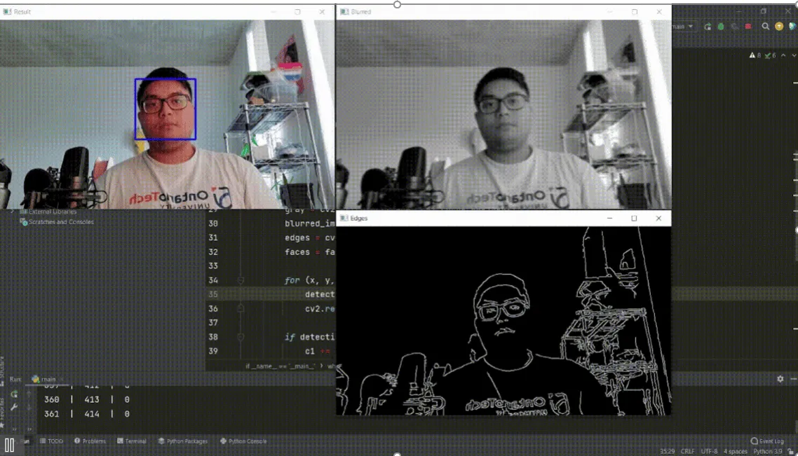
There is the need for the robot to be able to determine the number of people that are in its vicinity. This serves two purposes: keeping track of the current number of people in the room to gauge how long it needs to disinfect that area, and also to be able to interpret this data so that the next decision can be made as to where the robot will go next. Currently, this involves the use of the Logitech C920 3MP 1080P HD USB mono camera with a diagonal field of view of 78 degrees. This camera is used for face detection using pre-trained haar cascade models with openCV classifiers. The premise of this technology is that there are particular features that the camera can distinguish, which in this particular case are called haar features. Displayed in Figure 24 below, the algorithm requires that these distinct light and dark haar features are utilized to train the classifier. The first image on the left with the horizontal white and black bars are supposed to represent the brow of the face. The transition between the light and dark is something that the camera is capable of detecting. Likewise, the single white vertical line bounded by two black lines is the haar feature for the bridge of a nose. These distinct individual features are brought together to train the classifier so that it can analyze the pixels involved in the object.
Figure 24. Haar features derived from distinct areas on the face [6]
The cascade of classifiers is an approach to mitigate the amount of error in this process. The first step was to recognize that the majority of the image does not involve the face. The area that the face actually takes up on the image takes up a small fraction compared to everything else in the image. There are thousands of features that the camera can look for, but it would take too long to process anything tangible if it were to scan every pixel for certain haar features. Instead, the features are grouped together into different stages of classifiers that check sequentially. This means that if a certain area does not pass the first stage of the classifier, that region is disregarded and not checked for the remaining features.
Figure 25. Preliminary face detection algorithm overlay on recorded video
Currently, the system is not tuned enough yet to detect faces accurately and rapidly. There is more work required to develop the accuracy and repeatability of the algorithm against varying backgrounds and distinct facial features. One area of potential improvement would be to implement body detection so that the algorithm can predict where the face will be quicker. A simple approach to this would be that the haar features used to distinguish a face would always typically be on top of the body feature. The team hopes that by adjusting the classifiers to include body detection, the rate at which false positives occur and missed faces will be drastically reduced.
The autonomous navigation system remains unchanged from the previous design and physical components were transferred to the new design chassis. Tweaks to the code were needed to accommodate the design change.
In order to achieve both effective disinfection and efficient autonomous navigation, Robot Operating System (ROS), has be implemented in the embedded PC of the robot. The system is utilizing the NVIDIA Jetson Nano with ARM Cortex-A57 CPU with a Maxwell GPU. ROS serves as the framework for the software architecture and development and is also the central point of communication across the different devices. In order for the robot to navigate autonomously, a map needs to be created for the robot to use during operation. Visual simultaneous localization and mapping (V-SLAM) is a process which determines the position and orientation of the robot with respect to its surroundings, while simultaneously mapping the environment around the sensor obtaining that data. Thereafter, ROS interprets the information gained from the map and send motor commands accordingly to the microcontroller unit to move the robot.
Figure 26. SLAM driven by Intel Realsense L515 using RTABMAP packages for localization
The team is currently utilizing an Intel Realsense L515 2D lidar camera which is the sensor responsible for collecting the data for SLAM, as displayed in Figure 26. Although the majority of the mapping algorithm will be handled by packages that come with RTABMAP, a lidar-SLAM-based algorithm, localization information must still be fed into the algorithm. The pose of the robot is achieved by Dead Reckoning, which is a process of calculating the current position of the robot by using its previous position, speed, direction, and elapsed time. It is able to determine all this information from the encoder data from the VEX 775 Pro motors that drive the robot, which will allow odometry information of the robot to be calculated. There is an onboard inertial measurement unit (IMU) inside the L515 that is used to compensate for errors from Dead Reckoning. The encoder data are relative measurements and the error is therefore unbounded which means that it will compound so long as the system is running. By using Dead Reckoning, the IMU inside the L515, and visual localization from the Intel Realsense camera, the robot will be properly localized in the map created from RTABMAP, achieving autonomous navigation using the navigation stack available to ROS.
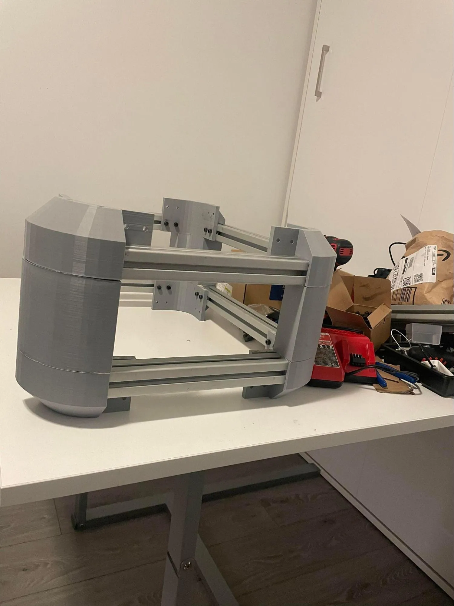
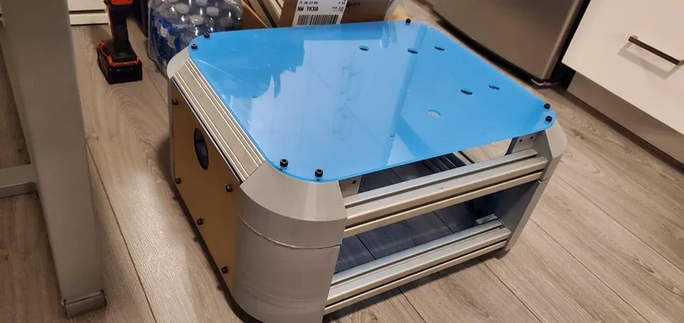
Our prototyping process consisted of two assemblies; the top filtration assembly, and the bottom navigation assembly. In terms of functionality, these two components serve different purposes as their names suggest, and come together to form the autonomous disinfection robot.
Top Assembly
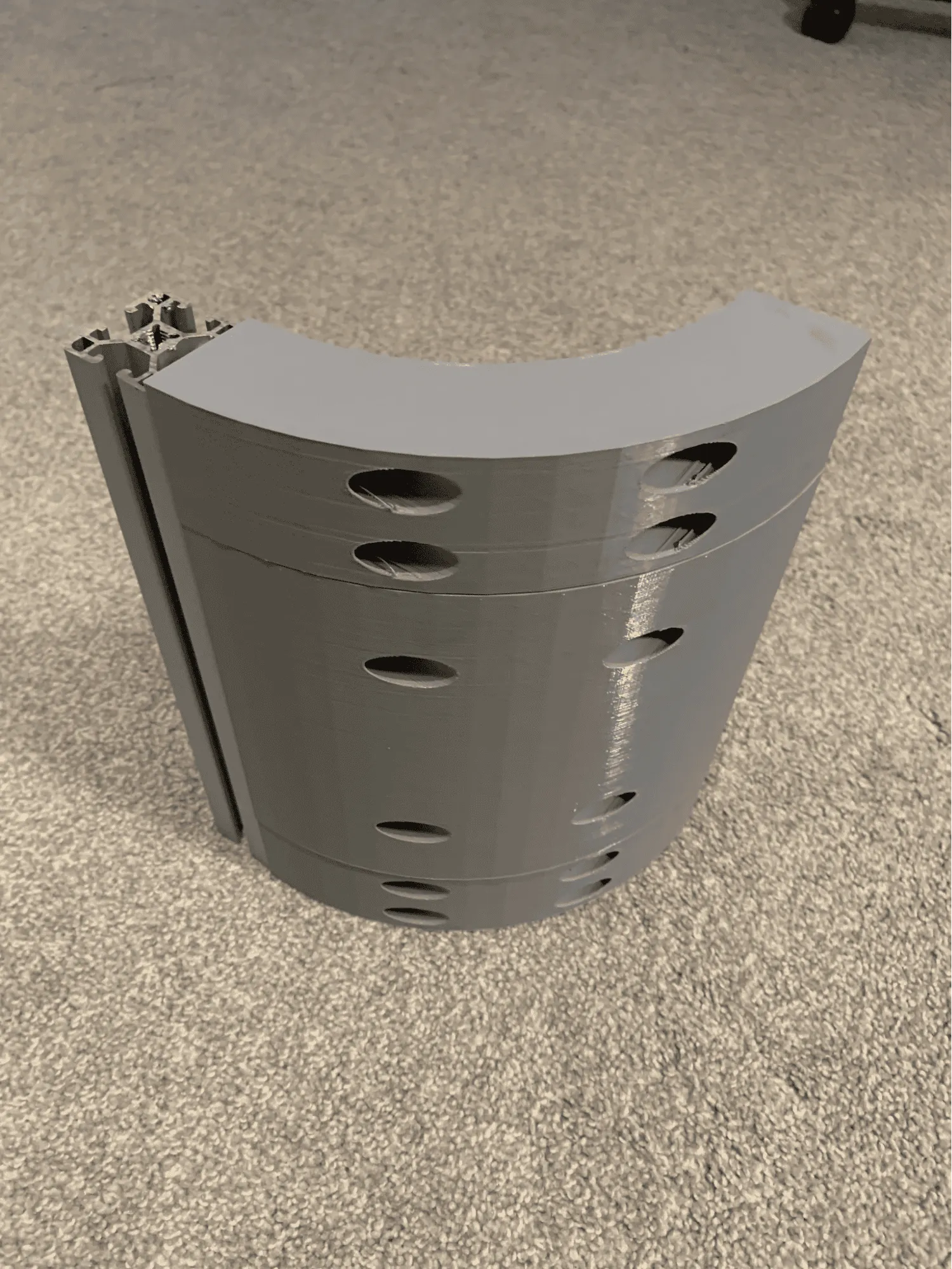
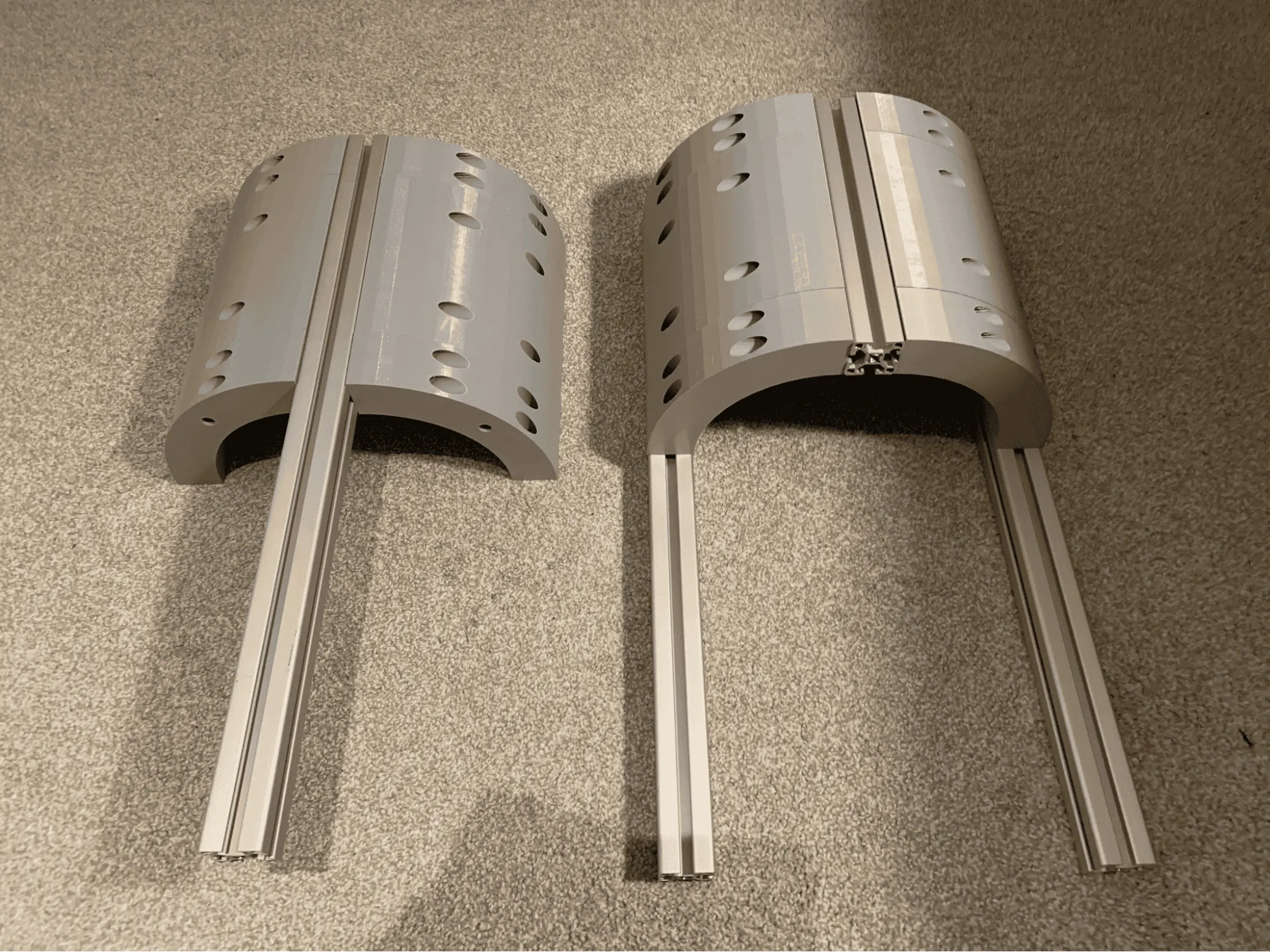
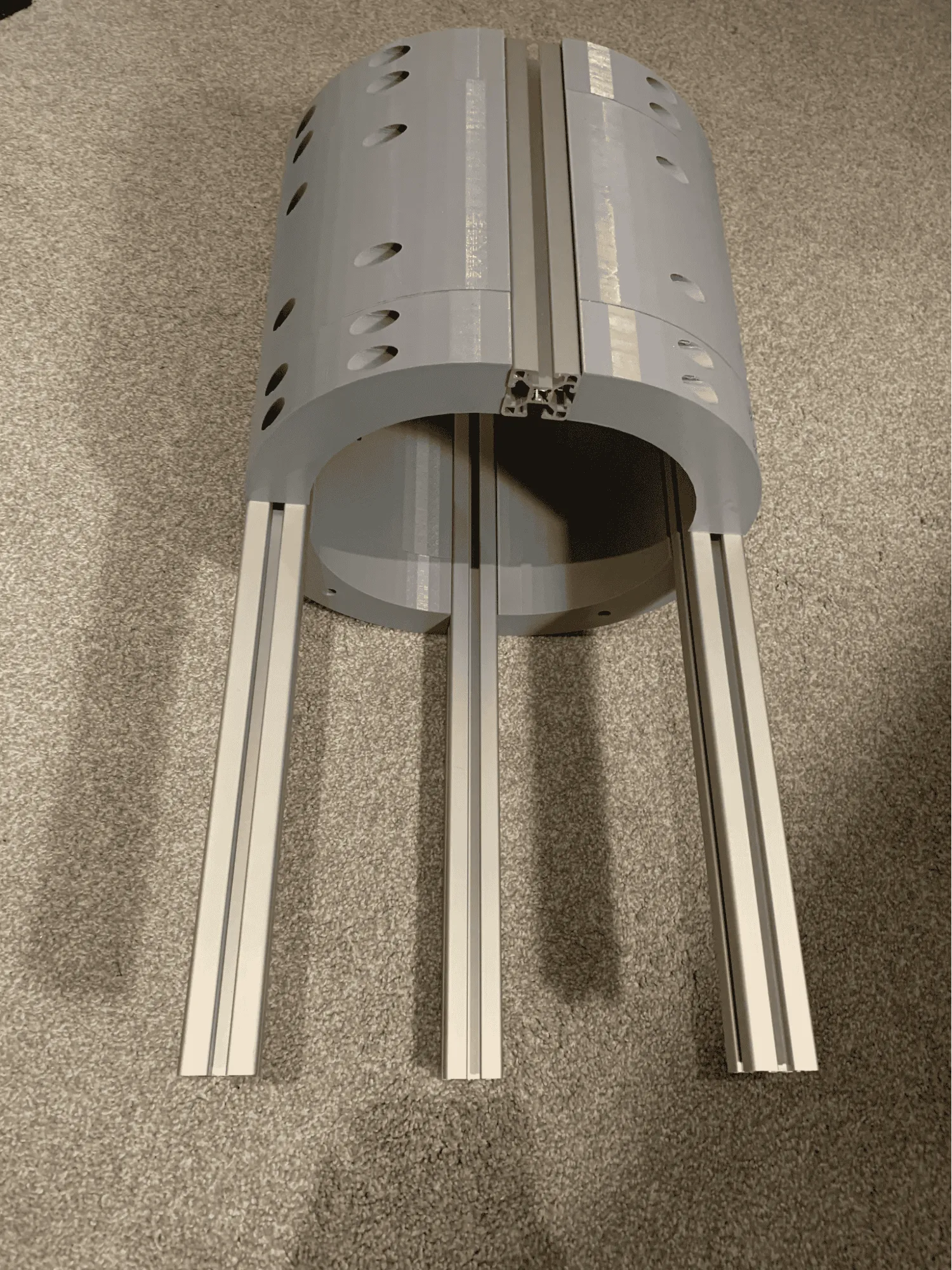
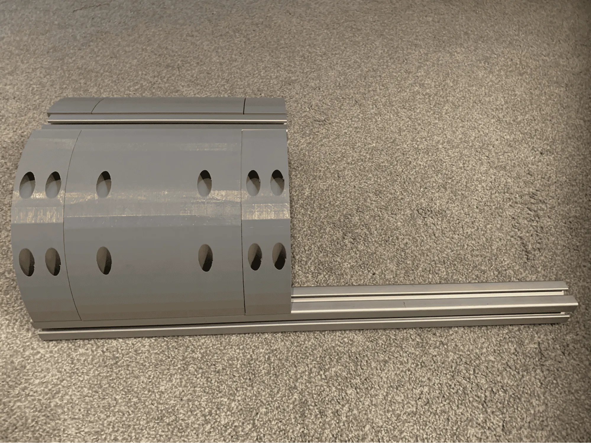
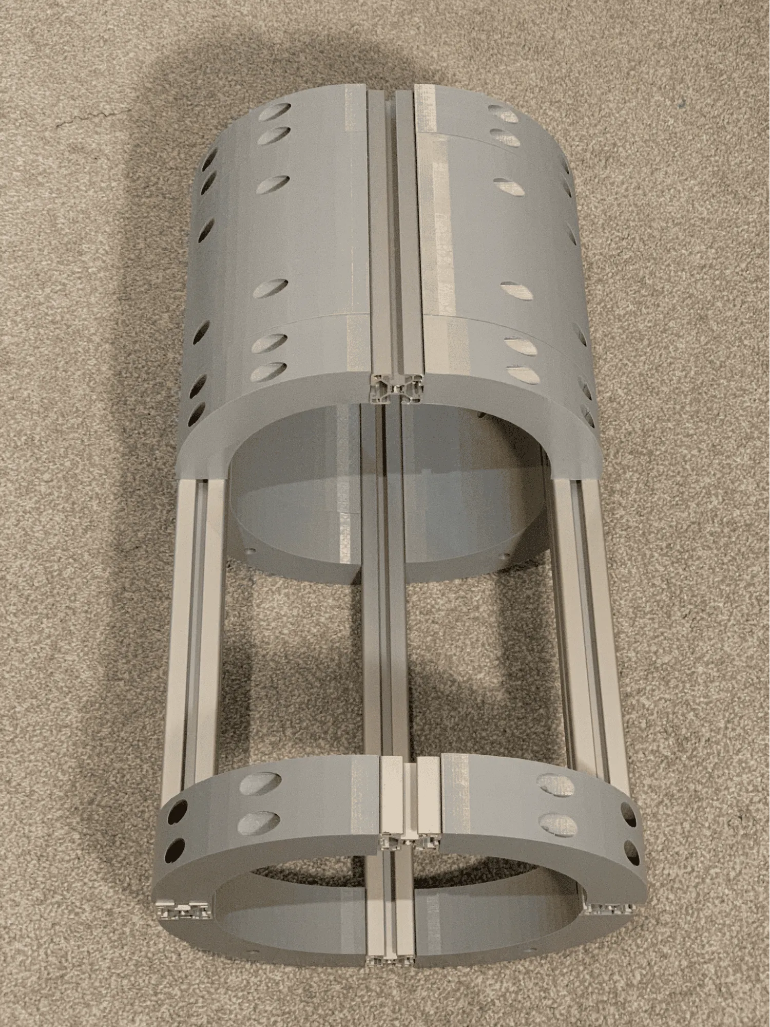
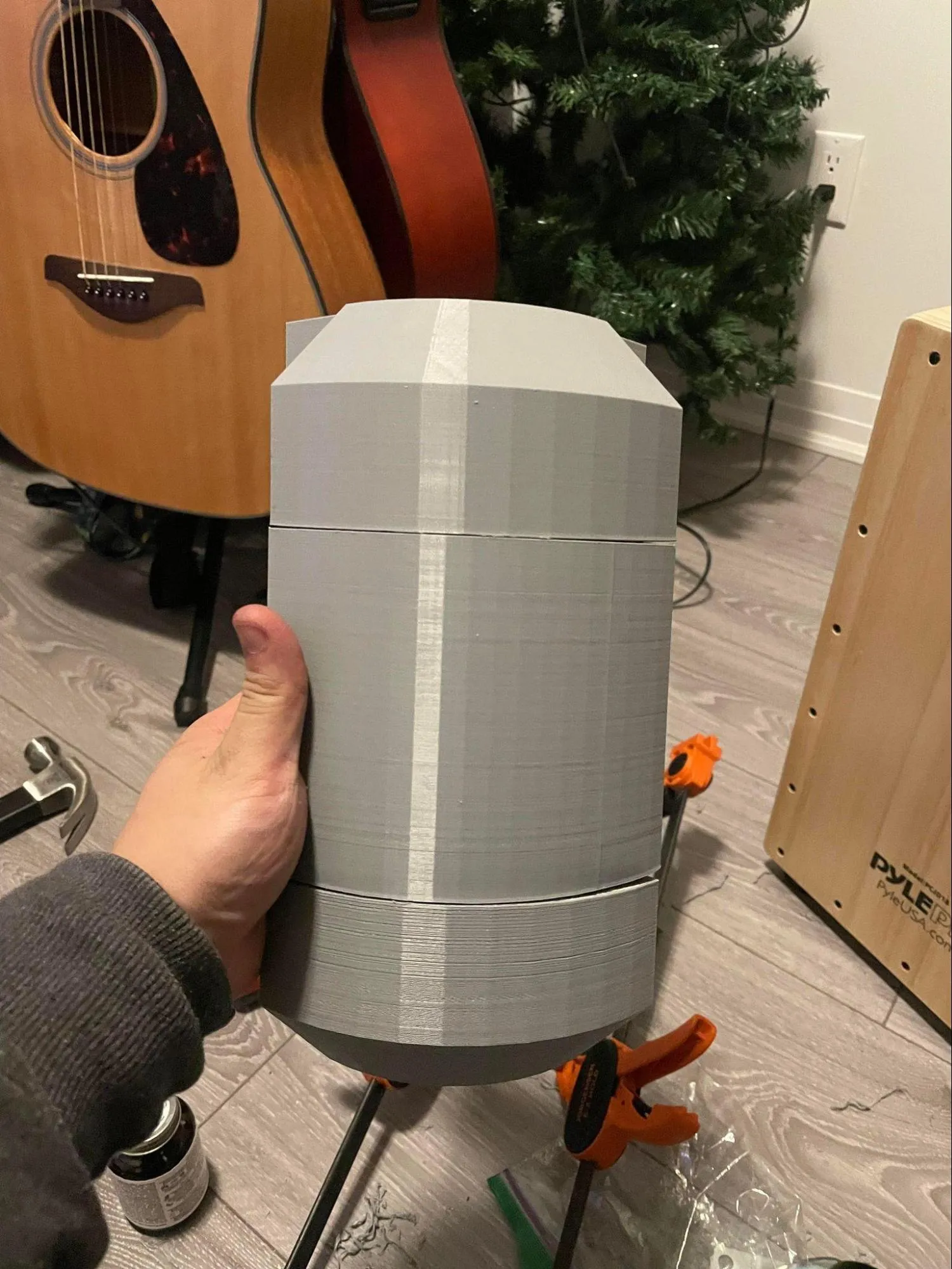
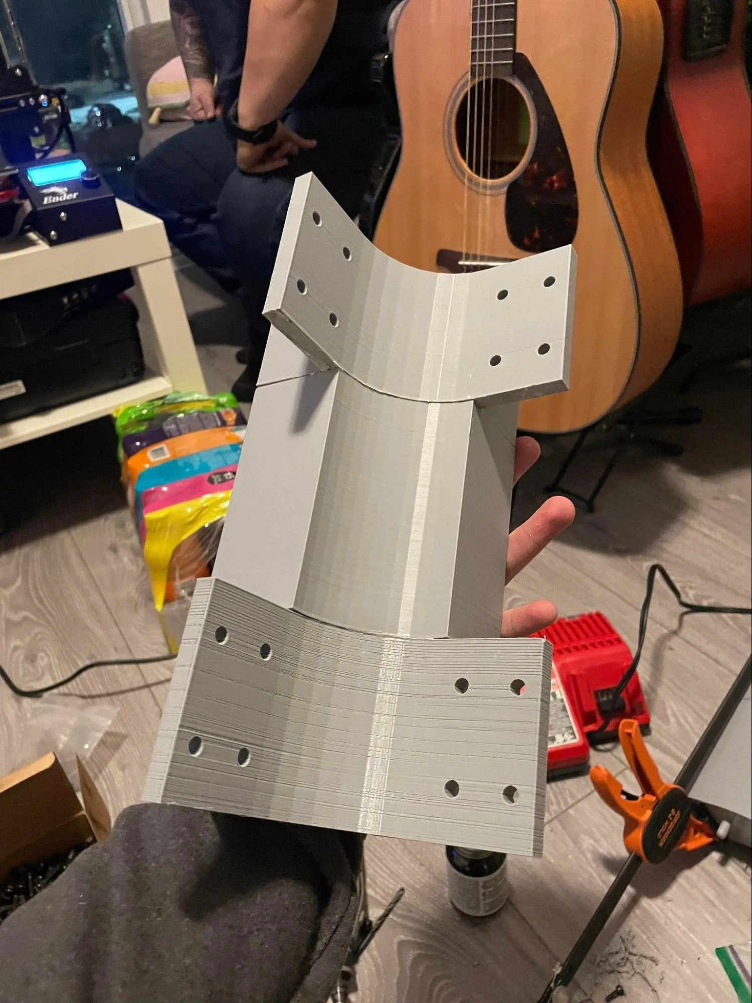
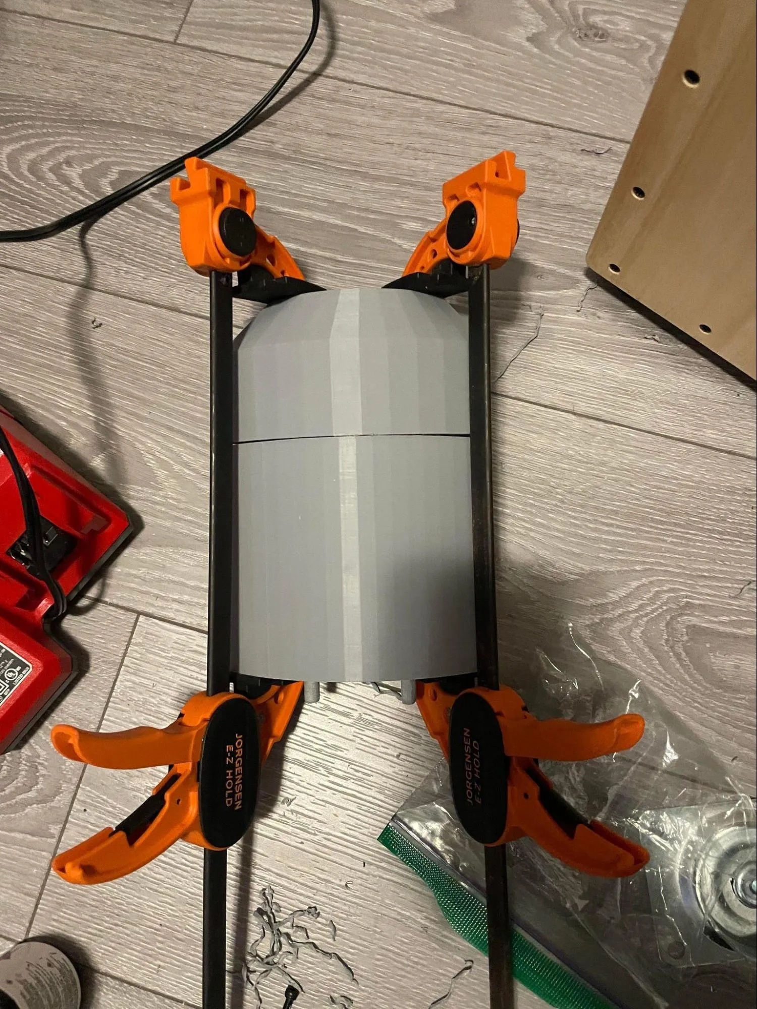
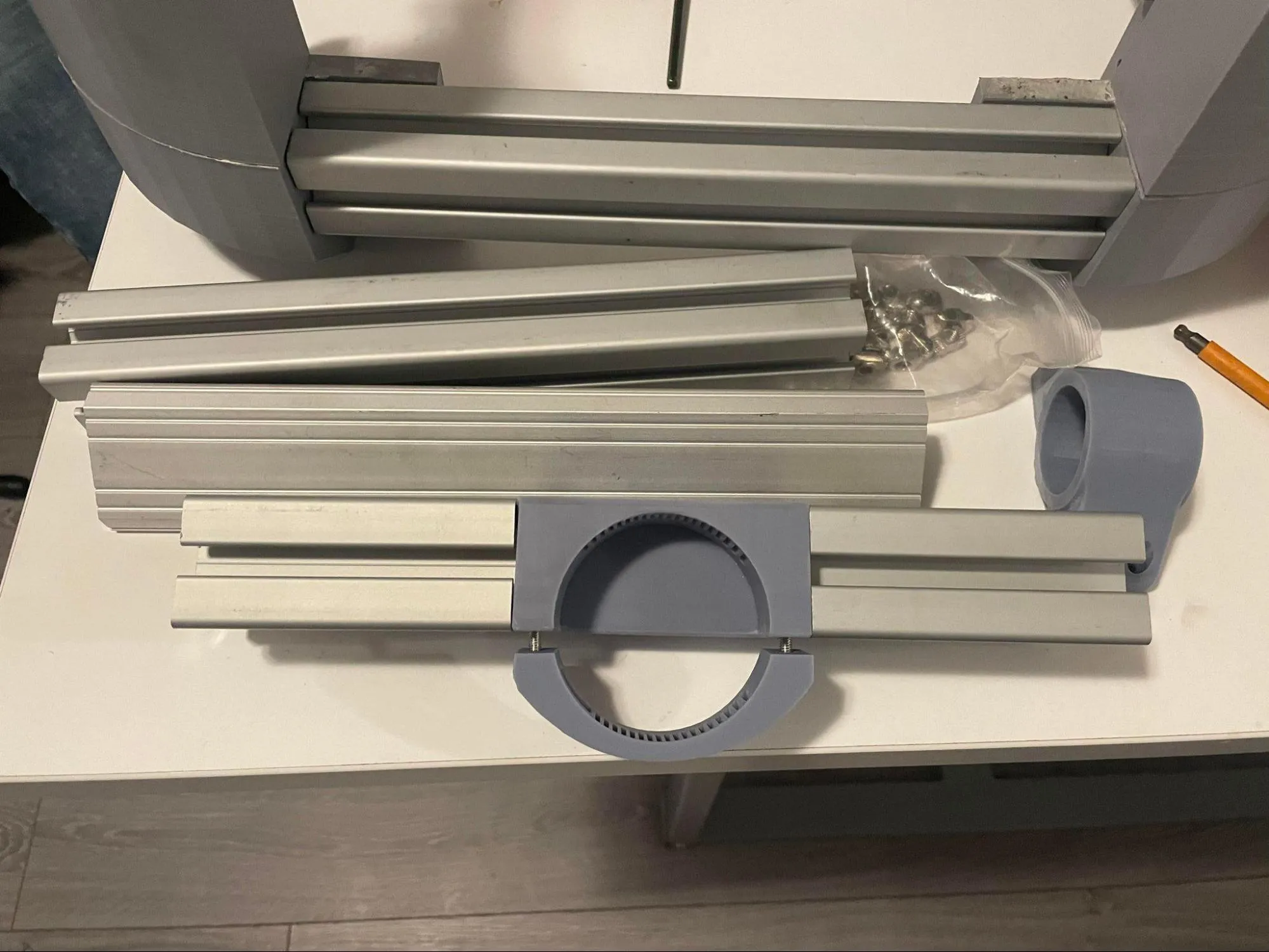
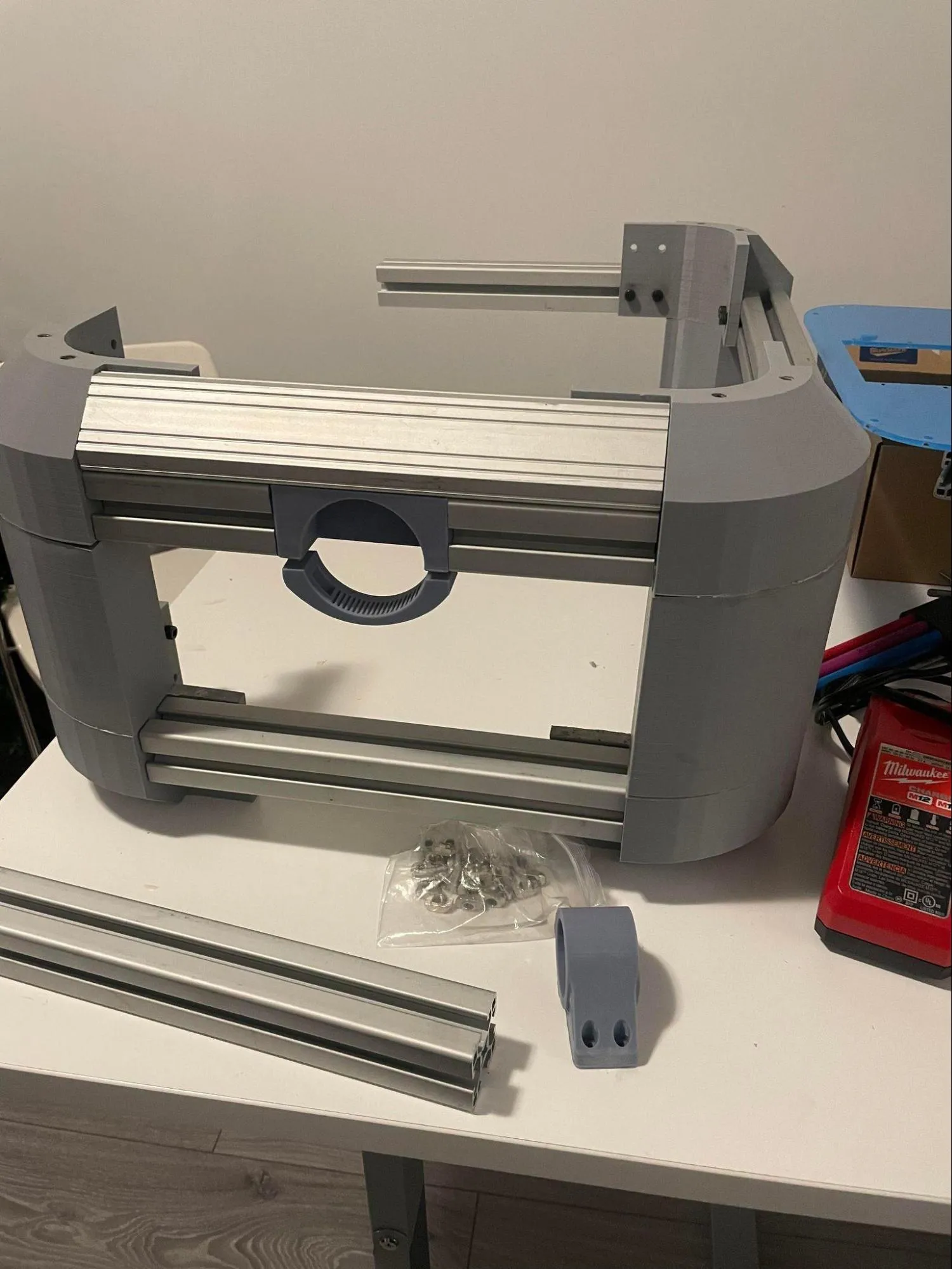
The main frame of the top assembly consists of aluminum extrusion and 3D-printed curved panels. The panels are connected to the extrusion using M6 x 25mm alloy steel hex socket bolts, and then tightened with M6 x 16.5 t-slot hammer head nuts. There are sixteen 3D-printed panels in total that connect to the extrusion for the top assembly. Twelve of the panels are used in the top half and four panels are used in the bottom half. Due to the size restrictions of the available 3D printers, it was decided that it would be best print several smaller pieces, which would also support a modular design. Figures C-1 and C-2 display the assembly process for the main frame of the top assembly.
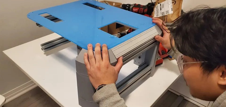
Following the completion of the main frame, the acrylic panels could be installed. These acrylic panels protect the main frame and the contents inside of it, and also have the added benefit of enhancing the aesthetics of the design. To determine the amount of acrylic needed, calculations were completed for both the top and bottom assemblies to determine the total surface area covered by these panels. 2026 in2 of 2.5mm thick acrylic, and 658 in2 of 5mm thick acrylic was required. The acrylic was laser cut. The top and bottom acrylic filter panels (8 pieces in total) were heat formed against the curvature of the main frame. The acrylic was also used for the implementation of maze and ventilation panels. Figure C-3 displays applications of the acrylic and Figure C-4 displays what the top assembly should look like following the installation of the acrylic. After the acrylic has been installed, the only thing remaining for the top assembly would be to house the relevant filtration pieces (fan, filter, UV lights).
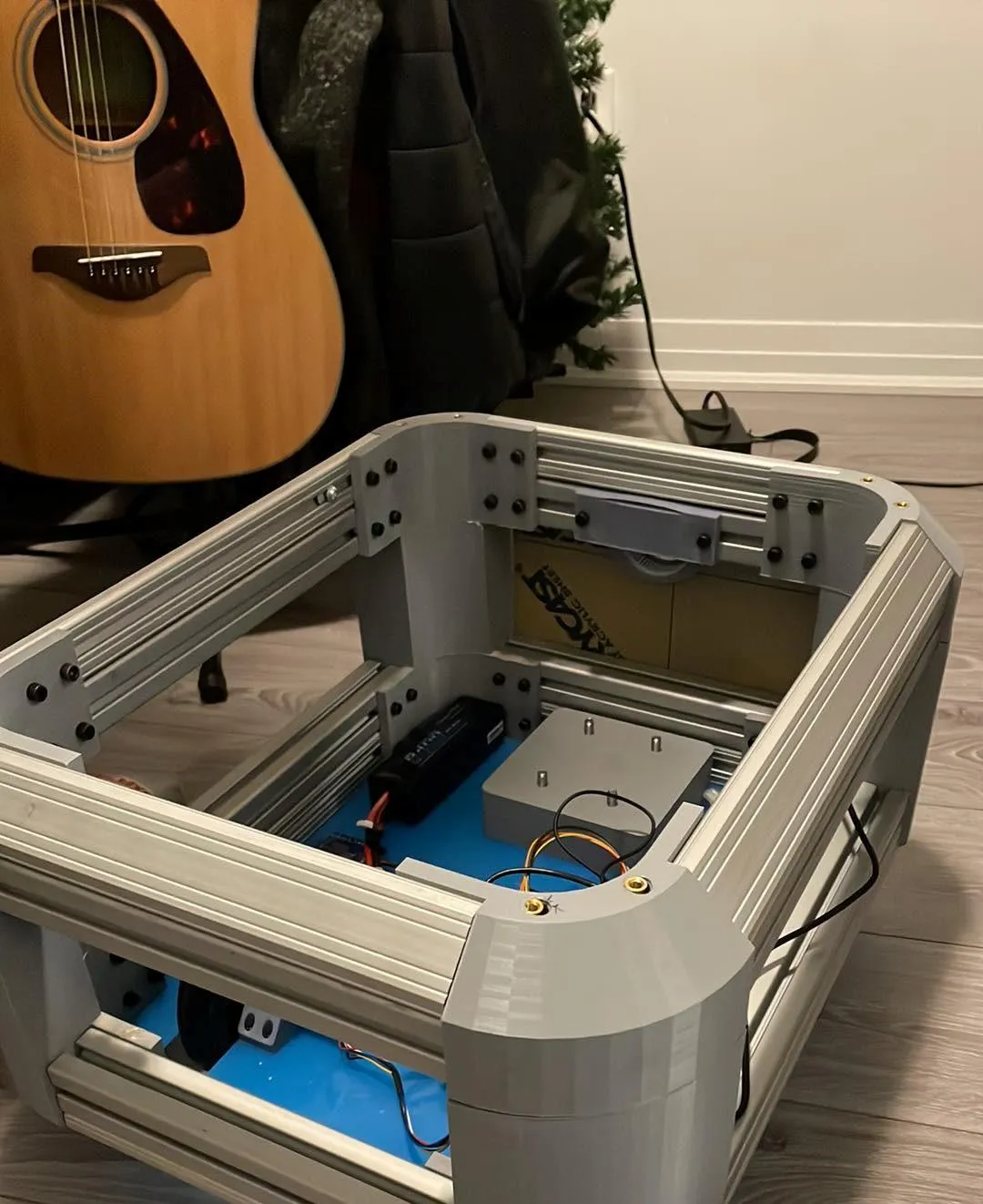
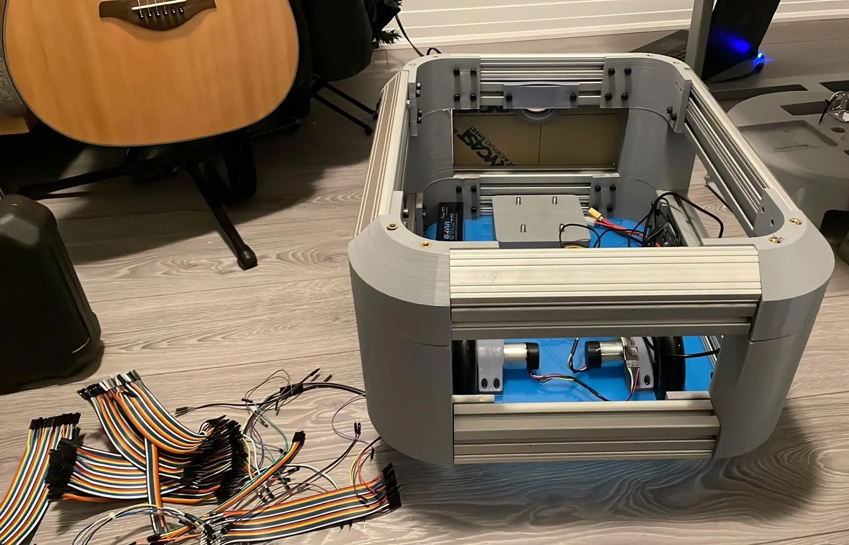
Bottom Assembly
The main frame of the bottom assembly was completed in similar fashion. The bottom assembly takes on more of a square shape, and so the 3D printed pieces are connected to the extrusion along the corners. Each set of 3D printed pieces were glued together for each corner.
Next, the acrylic panels were installed to hide and protect the electrical components inside of the bottoms assembly.
Finally, the electrical components were mounted and configured accordingly on the bottom plate. This process is displayed from Figures C-5 to C-10.
The FMEA is located in Table D-1 . Severity, occurrence, and detection were rated on a scale from 1 to 10. High severity was ranked with the number 10, high occurrence was also ranked with the number 10, and high detectability was ranked with the number 1.
The product manual is located in Appendix E. It contains information including the instructions for assembly, delivery, installation, employment, and maintenance, retirement and recycling of the product.
To ensure that the prototype functioned as expected and met the engineering requirements several laboratory tests were performed. These included testing of materials, sensors and actuators, air flow, air quality, software and mapping.
It was decided collectively as a team to utilize acrylic for certain panels due its ease of machinability and lightweight characteristics. However, it was a concern when the motor mounts were attached to the acrylic panel. One of the necessary tests that needed to be performed was to validate the robustness of the acrylic panel against various loading conditions. Therefore, as a part of the engineering specifications, it was determined that the robot should be able to withstand an additional 50 lbs of force applied overtop the wheels. As there was a limitation on the equipment used for testing, it was found that modifying ASTM-D5023 would best suit this scenario. ASTM-D5023 examines the dynamic mechanical properties of plastics in flexure via three-point bending [8]. The main principles behind the controlled experiment was that the specimen would be subjected to a bending moment. As the specific case for this experiment is with regards to the 4.5 mm acrylic panel connecting two motor mounts, it was determined that it has the same setup configuration. As a result, all that remained was a central load equidistant from both wheels that would apply 50 lbs of force onto the acrylic.
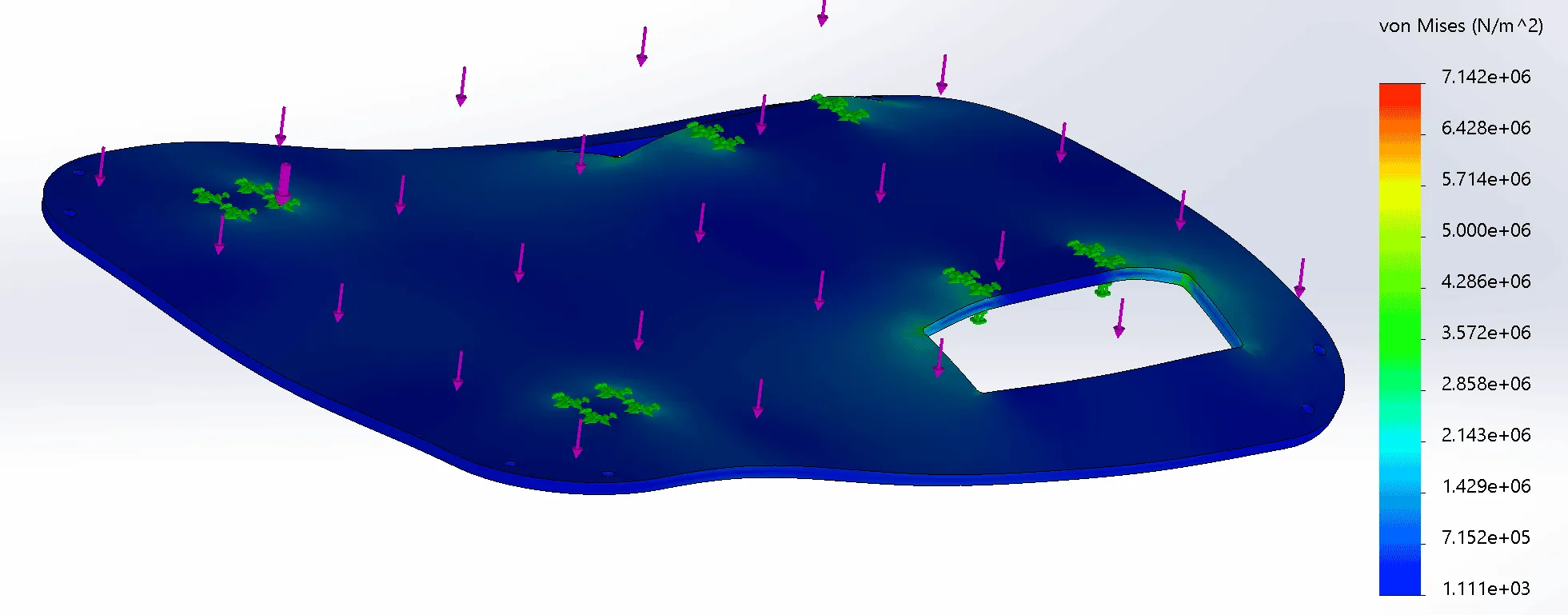
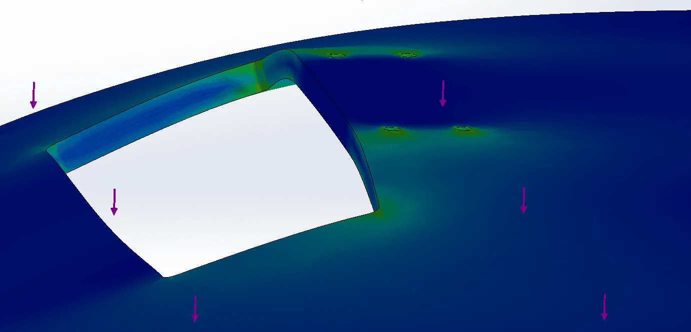
The bottom plate was the critical panel that needed to be tested as it was the load bearing panel. Acrylic is known for its strength-to-weight ratio and impact resistance [9]. When running the finite element analysis for the acrylic panel, the points that were touching the ground were set as the fixed points. It was observed that the stress at these points would be greater than the rest when a 50lb of force was applied. As dispalyed in Figures 27 and 28, there is a greater concentration of stress at the point of the two holes. The simulation shows that there is a likelihood that if the acrylic were to fail, it would do so at this location.
Figure 27 - Acrylic material load testing with 50 lbf
Figure 28 - Acrylic material load testing with 50 lbf, stress concentration
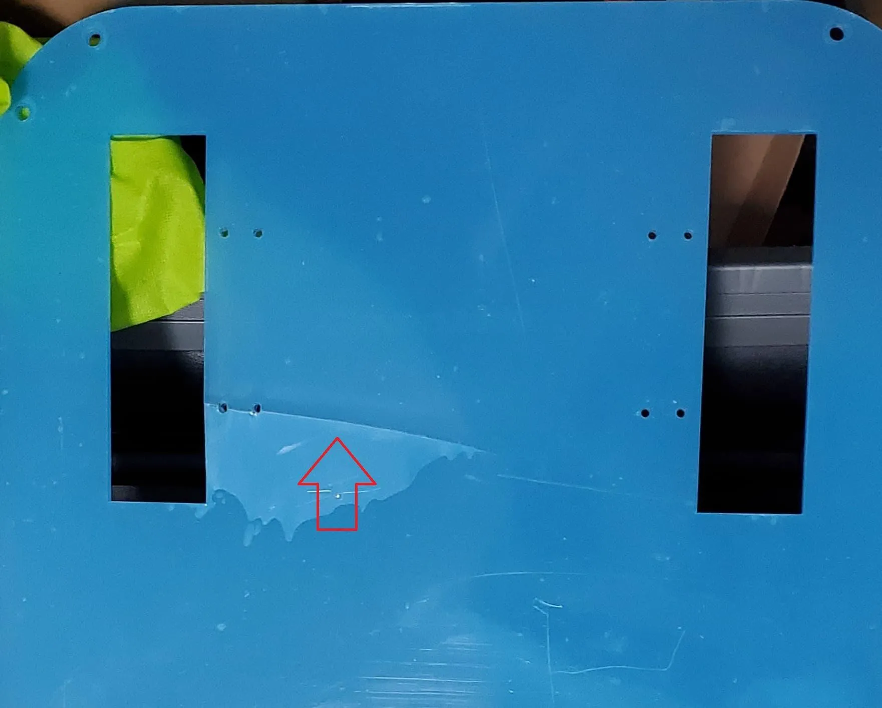
The team utilized a 50 lbs dumbbell and applied its weight overtop of the robot base. The results were in fact what was predicted. The fracture occurred in the same direction as the two holes were, as shown in Figure 29. As this is clearly an undesirable result and meaning that it did not meet the engineering specification set earlier, a new material choice had to be made. Due to material limitations, the next available material that is machinable, affordable, and has greater toughness, was medium density fibers (MDF). The test was repeated again and the MDF did not deform under load.
Figure 29 - Fractured acrylic stemming from the point of high stress by the two holes
One of the other concerns that required attention was the specific motors used on the robot. As the motors were supplied to the group, it was imperative to validate that the motor produces enough torque when fully assembled to ensure that it can travel its desired speed given the specifications of the battery. In the initial onset of the design process, it was determined that the robot should be able to reach an average walking speed of 1.2 m/s [10]. The robot did not need to reach fast speeds, but it should be able to make a decent pace in order to ensure that it could reach multiple areas within the floor in good timing. There were no clear testing methods within the ASTM that would outline the best approach to validating this area, therefore, a series of two tests were conducted to evaluate the motor speeds at various PWM ranging from 0 to 255 while controlling the overall weight of the robot. A test was done to measure the response of the wheels at no-load and another series of tests were conducted when the robot had an additional 50 lbs added to it.
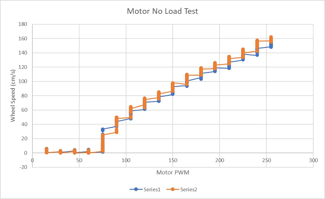
First the motors on the chassis were tested without any load to see how the individual motors would perform when increasing the PWM signal from 0 to 255. The loaded testing was done by running the robot on the ground over a certain amount of time, and the no-load test was done by mourning the motors so that they were not touching the ground. In this case a load is defined as the weight of the chassis along with the expected weight of the filtration unit and components. The no-load test results showed that the wheel speeds for the left and right motors performed quite similarly. In Figure 30, the Series1 line is the left motor, while the right motor is shown by Series2.
Figure 30 - No-Load Motor Test (Series1 Left Motor, Series2 Right Motor)
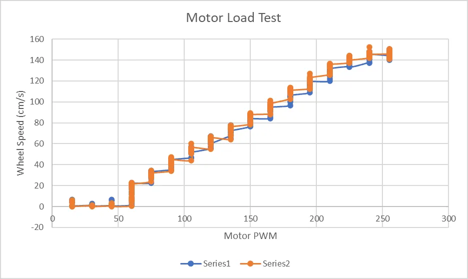
As shown in Figure 31, after applying the load on to the motors it can be seen that there is little difference other than the fact that the loaded results show that the maximum speed of the motors is reduced slightly. This is to be expected as there is additional weight that it must carry within the same time limits of the no-load test. Additionally from these results, an equation can be obtained for the speed of the motor with respect to the PWM input and can be later used to tune the PID speed controller of the motors.
Figure 31 - Loaded Motor Test (Series1 Left Motor, Series2 Right Motor)
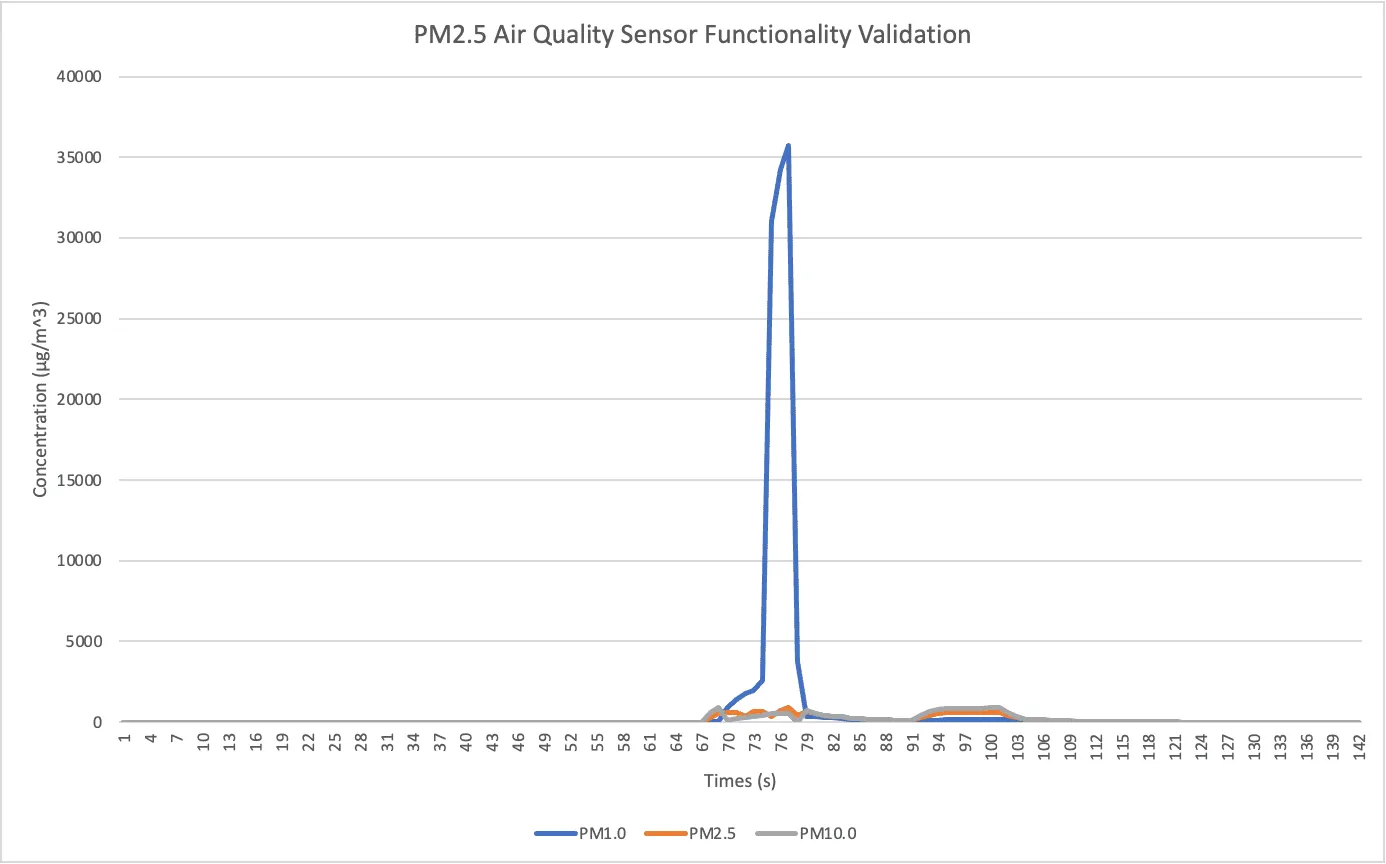
According to bioaerosol scientist Dr. Byung Uk Lee [11, p. 4], “...the minimum size of a respiratory particle that can contain SARS-CoV-2 is calculated to be approximately 9.3 µm.” With this knowledge, we purchased a PM2.5 air quality sensor. PM2.5 refers to particulate matter that is less than or equal to 2.5µm in diameter. This sensor was able to detect the concentration of PM1.0, PM2.5, and PM10.0 in the environment. The next step was to validate the functionality of the PM2.5 air quality sensor. The sensor was placed in a room and exposed to clean air. After a few seconds, solder smoke was introduced to the system to identify if the sensor captured the change. From the serial monitor, it was identified that the data experienced an immediate and drastic increase due to the detection of PM1.0, PM2.5, and PM10.0 sized particles. This data is displayed in Figure 32. Therefore, we were able to confidently validate the functionality of the PM2.5 air quality sensor.
Figure 32 - PM2.5 Air Quality Sensor Validation
To test the airflow of the unit, an Aiomest anemometer was used. The airflow test is based on the ASHRAE standard 111 airflow tests for circular ducts. In the ASHRAE tests, 3 holes are made in a duct 60-degree angles apart from each other, a probe is inserted into the duct, and readings are taken at six points along the traverse from one side of the duct to the other [12]. The average velocity of the airflow is then multiplied by the cross-sectional area to obtain the volume flow rate.
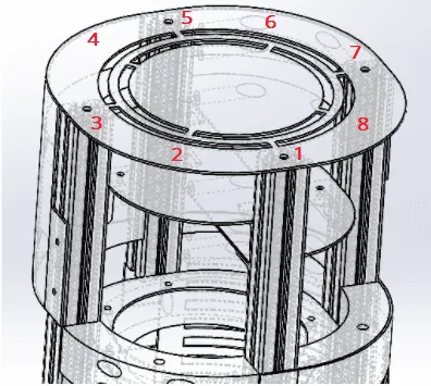
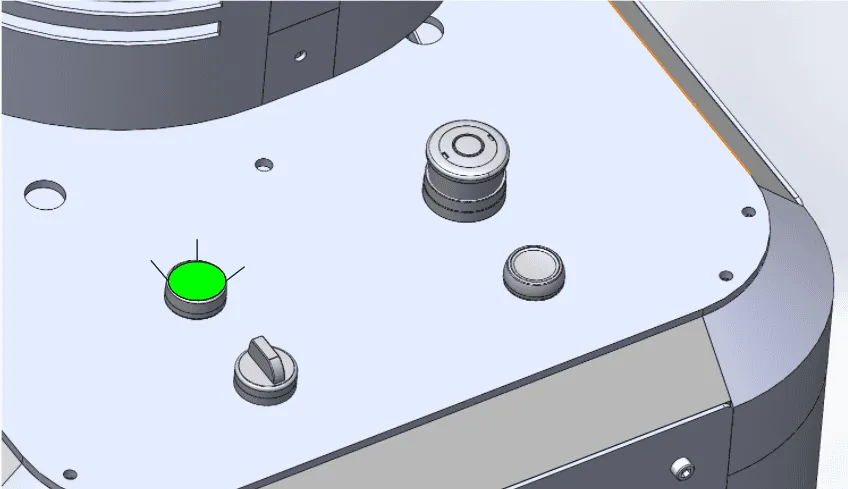
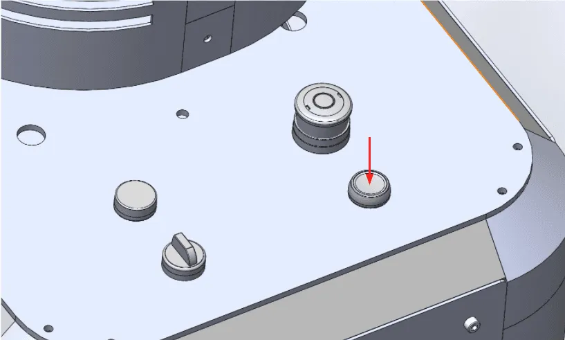
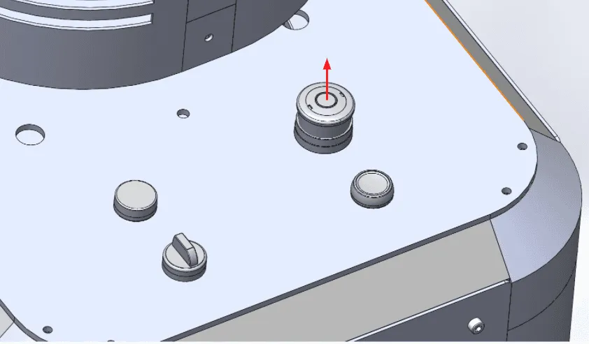
The airflow test for this unit was similar to the ASHRAE test with some modifications since the airflow is being measured at an outlet rather than in a duct and the flow is somewhat obstructed. On the top piece of the filtration unit, there are two circles cut out, this is where the air flows out. The anemometer was used to measure the airflow at points 1 through 8 as displayed in Figure 33 on the outer circle and the inner circle for a total of 16 readings.
Figure 33 - Airflow Measurement Points
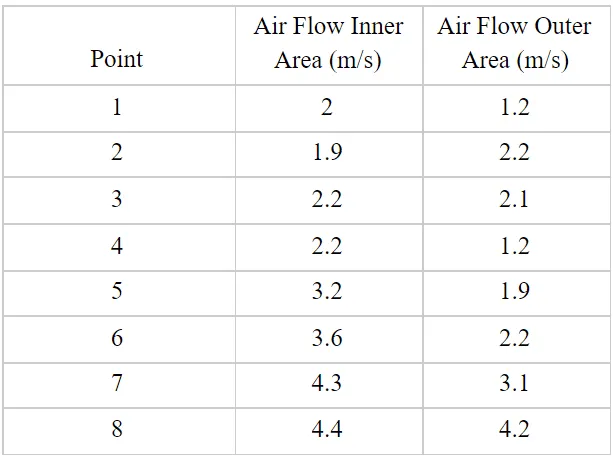
The results from the anemometer readings for the airflow test are displayed in Table 1. The average of the air velocities was taken and found to be 2.6 m/s. From Solidworks, the area of the openings on the top panel was found to be 0.013223 m2 . Multiplying the average flow rate and the area results in a volume flow rate of 0.0346 m3/s or approximately 72 cfm.
Table 1. Air Flow Test Results
Previously it had been determined that a CFM of approximately 300 is required for a 250 ft2 space (medium sized office) with a 9 ft ceiling and 8 Air Changes per Hour (ACH). Since the actual volume flow rate of the unit is 72 CFM, the unit can make about 2 ACH for the same sized room. These air changes are in addition to the ventilation already provided in the rooms.
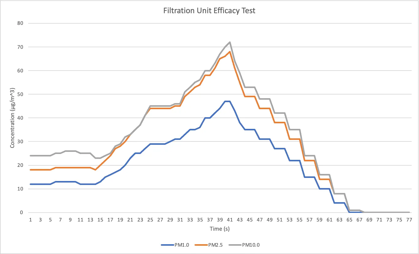
After the functionality of the PM2.5 air quality sensor was confirmed, the air quality sensor was placed in the maze chamber as close to the disinfected air as possible and tested under a variety of conditions. Since the minimum size of a SARS-CoV-2 respiratory particle is approximately 9.3 µm, we could be confident that all COVID-19 sized particles had been eliminated if our system reduced the concentration of PM10.0 to zero. Furthermore, HEPA filters can theoretically remove any airborne particles with a size of 0.3 microns (µm) [13]. Therefore, as long as the HEPA filter successfully captures particles within its theoretical threshold, we can conclude that after having passed through the HEPA filter, the air is fully disinfected of COVID-19 respiratory sized particles.
Figure 34 - Filtration Unit Efficacy Test
Figure 34 outlines the results of our filtration efficacy test. We conducted this test in a small room and it lasted for approximately one minute. The sequence of steps were as follows:
Therefore, from this test, we can conclude that the filtration system is successful in removing COVID-19 sized particles. It can also be concluded that this air filtration unit meets the engineering requirement of getting air to a quality of 30 or less on the EPA air quality index (AQI), as for a concentration of zero the AQI value is zero [14].
A software model of the disinfection robot was used in conjunction with ROS and Gazebo to simulate the virtual indoor environment and tune the motor controls. Multiple tests were conducted to tune the facial detection algorithm. The tests were performed in indoor conditions using a video in which a face was present 100% of the time. Using this information, the accuracy of the algorithm was calculated by determining the amount of frames that a face was detected out of the total amount of frames in the video. The false positive detections were measured by counting the number of frames in which there were multiple bounding boxes present, since there was only a single face in the test video this method was sufficient for identifying false detections. The rest of the tuning was based on trial and error and visual observations. The tuning parameters were the types of image blurs as well as the kernel size for each blur. From testing the image blurs with the video results, it was found that using a gaussian blur of size 5x5 would eliminate most of the noise in the image while allowing for the detection to be consistent. This eliminated most of the missed detections that occurred, however, there were still a number of false detections.
Figure 35. Tuning Results
Figure 36. Image Blur Results
Upon further testing it was realized that the best combination of blurring included the use of a combination of gaussian and median blurring. The kernel sizes were 5x3 and 3 respectively. It is evident from Figure 36 that using a rectangular gaussian kernel to blur the image allows the frame to preserve more of the horizontal facial features that help the detection algorithm locate haar features. It is important to note that the edge detection is done using a canny edge detection algorithm. This was used to visualize the effects of the image filtering on the input image, to help make visual observations for manual tuning of the kernel sizes. Currently, the occupancy detection algorithm offers a 90% detection rate with no false detections. The missed detections are due to the profile of the facial features being hidden when the subject is turned sideways.
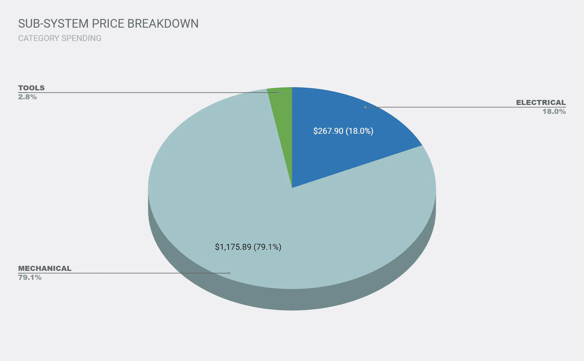
The bill of materials was used to keep track of purchases delivery date, price, and quantity and ensure that the project was complete within budget. Google sheets was used for this purpose. Figure 37 shows the price breakdown by sub-system, as shown most of the budget was allocated to purchases for the mechanical sub-system. The most expensive purchases being the fan, aluminum extrusion, and PLA filament. Please see appendix B for the full bill of materials.
Figure 37: Sub-system Price Breakdown
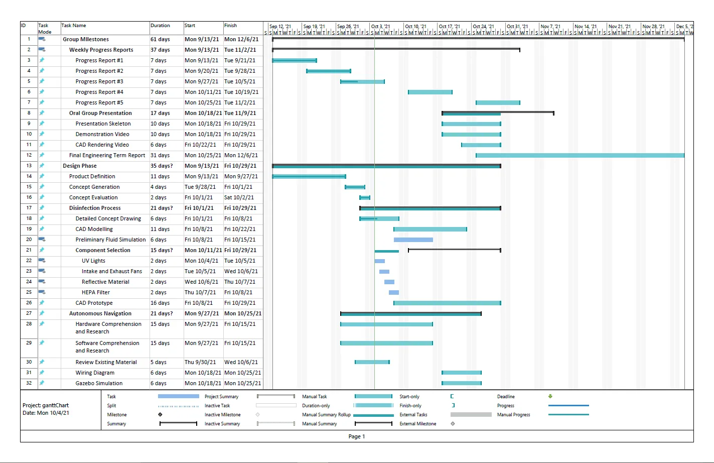
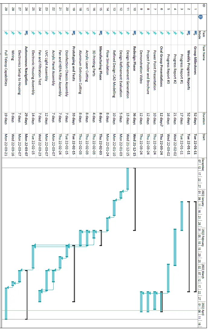
See Appendix A for further details regarding the project planning phase for both the fall term and winter term. These Gantt charts were created in order to properly plan the project timeline and meet all the necessary milestones. The purpose was to bring deadlines and project tasks into light and include team member responsibilities. The Gantt chart was created on Microsoft Project and outlined the major components to the Capstone project.
There are certain ethical considerations that went into the preliminary design of the robot. One of the necessary information that the robot needs is to be able to determine the level of occupancy in a particular zone. This information drives the decision tree on where the robot should go next. Currently, the team has implemented a face detection system to count how many people the robot encounters. There is speculation whether using face detection as a method to keep track of the number of people is breaching people’s privacy, however, the system does not retain each person’s distinct face. This technology is not face recognition so this would not be able to identify an individual based on the data. Rather, the camera is taught to look for certain distinct features in its path, which uses the two eyes and a central nose as a distinguishing feature. The system in its current state is incapable of associating a certain feature and assigning it to a specific individual and neither does the development of the robot require this. Therefore, The ethical considerations behind facial detection is one that may be a growing concern but there should not be a concern for this application.
Another ethical consideration for the design and development of this autonomous disinfection robot was that it was intended to protect individuals from exposure to harmful bacteria and viruses in the air. The need was driven to provide a better means to disinfect an area without putting someone in harm’s way. There may be chatter regarding the application of an autonomous robot eliminates the need of a human worker that would have traditionally completed that task. The team recognized that this is also a growing concern as the world moves towards automation -- but a necessary step when safety is involved. The implementation of an autonomous robot to go in and disinfect dangerous bacteria and viruses is no different than a robot that is used to handle hazardous nuclear material. There is an inherent risk that is involved with a necessary job that society does not want to subject humans to do. Therefore, it is a reasonable step to try and mitigate these risks to humans through the application of autonomous robots. In addition, the design and development of this robot creates new jobs as someone will need to be capable of manufacturing the components, troubleshooting the errors that arise during operation, and manage the sales when it comes to purchasing and leasing. Effectively, eliminating a hazardous job creates multiple new ones that need to support it.
The UVC light used for disinfection can be harmful to humans. Exposure to UVC light can cause burns on skin and cause eye injuries [15]. These injuries can occur even after seconds of exposure. Due to the negative effects of exposure to UVC light it is very important to keep the UVC well contained within the disinfection unit. In the current design the UVC light is inside the housing which will also be covered by an external fascia. Fans may also be cause for a safety concern, as they can cause injury if someone accidentally sticks their hand in. The external fascia that will be added will ensure that people cannot put their hands near the fan while the robot is in use. The robot will operate autonomously in occupied spaces so it is important to ensure human detection will be accurate to avoid collisions. To do so a combination of sensors and cameras along with software algorithms will be used. Additionally there may also be unexpected reasons the robot may need to stop so it should be equipped with an emergency stop button.
The basis of this project was to create a solution for the safe disinfection of indoor spaces amidst the COVID-19 pandemic. These issues are primarily rooted in the fact that most industries continue to operate during the pandemic, yet are at risk of infection. Safe and efficient disinfection practices are necessary to facilitate a safe environment for the public.
The solution was a fully autonomous disinfection robot that utilizes a HEPA filter, UVC germicidal irradiation, and VSLAM technology. The robot is composed of two components, a disinfection unit and a navigation system. The disinfection unit is composed of two components: a filter system and a UVC system. A fan is mounted in the middle of these two chambers, effectively joining them. The fan pulls in air through the filter system at the bottom, which captures 99.99% of airborne particles with a minimum size of 0.3 µm. Surface disinfection of particles captured by the HEPA filter occur through the implementation of UVC irradiation. The air then travels to the maze section where airborne disinfection occurs through the implementation of UVC irradiation. Baffles are arranged in a maze-like configuration and serve to extend the travel time of air out of the system, in order to maximize the amount of UVC exposure. ROS was used to localize the robot using V-SLAM and send motor controls.
The solution was rigorously tested throught a variety of methods. All systems were examined on an individual basis and met the established requirements. After conducting an airflow test, the volume flow rate of air leaving the unit was found to be 72 CFM. For a 250 ft2 room with a 9 ft ceiling, this would provide 2 additional air changes per hour. From air quality testing, the filtration system proved to be capable of eliminating the concentration of PM10.0 in the environment. Since the minimum size of a SARS-Cov-2 respiratory particle is approximately 9.3 µm, the elimination of PM10.0 indicates the elimination of SARS-Cov-2 sized particles in the environment.
[1] M. Biasin, A. Bianco, G. Pareschi, A. Cavalleri, C. Cavatorta, C. Fenizia, P. Galli, L. Lessio, M. Lualdi, E. Tombetti, A. Ambrosi, E. M. A. Redaelli, I. Saulle, D. Trabattoni, A. Zanutta, and M. Clerici, “Uv-c irradiation is highly effective in inactivating sars-cov-2 replication,” Nature News, 18-Mar-2021. [Online]. Available: https://www.nature.com/articles/s41598-021-85425-w
[2] “ADIBOT: UV-C disinfection,” UBTECH Robotics. [Online]. Available: https://www.ubtrobot.com/products/adibot?ls=en.
[3] K. Ruan, Z. Wu, and Q. Xu, “Smart Cleaner: A New Autonomous Indoor Disinfection Robot for Combating the COVID-19 Pandemic,” Robotics, vol. 10, no. 3, p. 87, Jul. 2021.
[4] 产品与解决方案 - 上海钛米机器人股份有限公司. [Online]. Available: http://www.tmirob.com/products?cate=3.\
[5] “DSR: Products,” globaldws. [Online]. Available: https://www.globaldws.com/products-dsr
[6] K. Kadir, M. K. Kamaruddin, H. Nasir, S. I. Safie, and Z. A. Bakti, “A comparative study between LBP and haar-like features for face detection using opencv,” 2014 4th International Conference on Engineering Technology and Technopreneuship (ICE2T), Aug. 2014.
[7] P. Polyzois and S. Thompson, “Practical mitigation strategies for countering the spread of aerosolized COVID-19 virus (SARS-COV-2) using ventilation and HEPA Air Purifiers: A Literature Review,” Journal of Geoscience and Environment Protection, vol. 09, no. 09, pp. 166–197, 2021.
[8] "ASTM D5023 Dynamic Mechanical Properties (DMA) of Plastics in Flexure (Three-Point Bending)", MTS.com, 2021. [Online]. Available: https://www.mts.com/-/media/materials/pdfs/test-standards/100-336-901a_PlasticsD5023.pdf?as=1.
[9] Marla_Acme, Author. “The Advantages of Acrylic Plastic.” Acme Plastics, 21 Feb. 2020, https://www.acmeplastics.com/content/advantages-acrylic/.
[10] M. L. Callisaya, C. P. Launay, V. K. Srikanth, J. Verghese, G. Allali, and O. Beauchet, “Cognitive status, fast walking speed and walking speed reserve—the gait and alzheimer interactions tracking (GAIT) study,” GeroScience, vol. 39, no. 2, pp. 231–239, 2017.
[11] Lee, Byung. “Minimum Sizes of Respiratory Particles Carrying SARS-COV-2 and the Possibility of Aerosol Generation.” International Journal of Environmental Research and Public Health, vol. 17, no. 19, 2020, p. 6960., https://doi.org/10.3390/ijerph17196960.
9.4 Navigation Testing
[12] Measurement, Testing, Adjusting, and Balancing of Building HVAC Systems. American Society of Heating, Refrigerating and Air-Conditioning Engineers, 2017.
[13] EPA, Environmental Protection Agency, https://www.epa.gov/indoor-air-quality-iaq/what-hepa-filter-1.
[14] “Air Quality Index (AQI).” United States Environmental Protection Agency, 2012.
[15] Center for Devices and Radiological Health, “Ultraviolet (UV) radiation,” U.S. Food and Drug Administration. [Online]. Available: https://www.fda.gov/radiation-emitting-products/tanning/ultraviolet-uv-radiation.
[16] P. H. A. of Canada, “Government of Canada,” Canada.ca, 09-Mar-2021. [Online]. Available: https://www.canada.ca/en/public-health/services/canadian-biosafety-standards-guidelines/handbook-second-edition/chapter-16-20.html. [Accessed: 02-Mar-2022].
[17] F. Arceo and About The Author Facundo Arceo I decided to get into 3D printing a while back and didn't think I would run into so many issues; From printer malfunctions to troubleshooting common printer errors, “3D solved,” 3D Solved. [Online]. Available: https://3dsolved.com/is-pla-recyclable/. [Accessed: 02-Mar-2022].
[18] “What is pla? (everything you need to know),” TWI. [Online]. Available: https://www.twi-global.com/technical-knowledge/faqs/what-is-pla. [Accessed: 02-Mar-2022].
Figure A-1: ADIBOT-A Disinfection Robot
Figure A-2: UltraBot
Figure A-3: Smart Cleaner Autonomous Disinfection Robot
Figure A-4: Disinfection Service Robot (left), TMiRob (right)
Figure A-5: House of Quality
Figure A-6: Maze Approach
Figure A-7: Two-Chamber Approach with UVC
Figure A-8: Hybrid design approach
Figure A-9: Hybrid Disinfection with Bladeless Impeller approach
Figure A-10: Ionizer and Surface Cleaner Approach
Figure A-11: Ionizing Machine with Collector Plate
Figure A-12: Gantt Chart for Project Planning (Fall Term)
Figure A-13: Gantt Chart for Project Planning (Winter Term)
Table B-1: User and Engineering Requirements
|
User Requirement |
Engineering Requirement |
Explanation |
|
Safety when in use, Safety when people present |
Onboard Safety Switch, Remote Safety Switch |
Kill switch to shutdown main system, Robot to shut down remotely |
|
Navigate environments, Navigate when people present |
LiDar Sensor, Ultrasonic Sensor, Motion Sensor |
Equipped with LiDar, ultrasonic and motion sensors |
|
Provide clean air in indoor environments |
Enclosed UVC Air-Exchange design, have 30 or less on the EPA air quality index |
The robot has an internal UVC air-exchange disinfection design and the ability to measure air quality |
|
Autonomous Control, Able to navigate through people |
Autonomous Navigation Algorithm |
Robot must be implemented with an autonomous navigation algorithm |
|
Low cost, inexpensive |
Low cost material, low cost system, low cost controller |
Robot should use inexpensive materials, and the cost to manufacture the overall system and controller should be reasonable |
|
Quiet and looks good |
Low noise components, aesthetically pleasing design |
Robot should perform at a reasonable noise level and looks good |
|
Rechargable, long lasting battery |
Rechargeable design |
Robot should have some form of rechargeability |
|
Lightweight |
Lighter than 60 pounds |
Robot should be lightweight in design |
Table B-2. Concept Selection Matrix
|
Concepts(right) & Criteria(below) |
Concept 1 (Maze) |
Concept 2 (Two-Chamber) |
Concept 3 (Hybrid Design: Airborne & Surface Disinfection) |
Concept 4 (UV Disinfection with Bladeless Impeller) |
Concept 5 (Ionizer and Surface Cleaner) |
Concept 6 (Ionizer with Collector) |
|
Size |
+ |
+ |
- |
+ |
+ |
0 |
|
Weight |
+ |
+ |
- |
+ |
+ |
- |
|
Battery |
0 |
0 |
0 |
0 |
0 |
0 |
|
Cost of Production* |
+ |
0 |
- |
+ |
0 |
- |
|
Air Filtration* |
+ |
+ |
+ |
+ |
- |
+ |
|
Chassis Motor Speed |
0 |
0 |
0 |
0 |
- |
0 |
|
UV Light* |
+ |
+ |
+ |
+ |
- |
- |
|
Complexity of Material |
0 |
0 |
0 |
0 |
0 |
- |
|
Sensory Modules* |
+ |
0 |
0 |
0 |
0 |
0 |
|
Sum |
+6 |
+4 |
-1 |
+5 |
-1 |
-3 |
Table B-3: Bill of Materials
|
Component |
Quantity |
Description |
Link |
|
Fans |
8 |
Using an online CFM calculator, we were able to determine a CFM of approximately 300 is required for a 250 ft2 space (medium sized office) with a 9 ft ceiling and 8 Air Changes per Hour (ACH). Using this information, we found 120mm 12V fans to use in our design. These fans have an airflow capacity of 250 CFM and tentatively meet our requirements. |
|
|
HEPA Filter |
1 |
Germguardian’s HEPA Filter with an activated charcoal layer was selected. The charcoal layer adds an additional layer of protection and eliminates odors. The HEPA filter is the primary mode of disinfection in the robot. The first thing the incoming air passes through is the HEPA and so it must perform as intended. Since this is a replacement filter for existing air purifiers, we have confidence it will be up to the task. |
|
|
UV-C Germicidal Light |
7 |
Germicidal applications of UV-light require wavelengths in the UV-C spectrum (200-280nm). We found 12V 265 nm wavelength LEDs which meet our requirements. These lights will be mounted on the walls of the bottom chamber as well as on the walls of the maze. |
|
|
Quartz Glass Baffles |
2 |
Quartz offers high transmissibility rates of UV light, which is essential for our maze design. The particles passing through the maze must be disinfected constantly. To prevent the baffles from disrupting UV transmission, they must be made of this material. We found five 250mm x 100mm plates with a thickness of 2mm. |
|
|
Anodized Aluminum sheets |
4 |
Anodized aluminum sheets offer reflectivity and will increase the effectiveness of the UV light. These sheets will cover all sides of the disinfection structure. |
https://www.alustock.ca/anodized-aluminum-sheets-5005H14-satin-clear-black-bronze |
|
40 mm Aluminum Extrusion |
16 |
Aluminum extrusion is commonly used in the industry. It is known for its high strength-to-weight ratio and is also non-magnetic. The internal components will be housed within an aluminum extrusion frame and covered by face plates. |
https://www.mcmaster.com/aluminum-extrusions/t-slotted-framing-rails/ |
|
45 mm Aluminum Extrusion Single Radius |
12 |
These T-slotted framing rails provide a nice, finished edge to the aluminum extrusion chassis. The radius rails give a finished appearance and ensure that the sharp edges are not exposed. They are set to 45 mm specification to allow a 2.5 mm gap on each side to provide a mounting surface for the face plates. |
|
|
Slot Bar Corner Gussets |
32 |
These T-slotted corner gussets will provide structural support for the aluminum extrusion frame. |
|
|
VEX 775pro Motors (x2) |
2 |
The VEX 775pro motors are commonly used in robotic applications and are capable of high speeds and moderate torque. |
|
|
Motor Driver |
1 |
These motor drivers are capable of handling voltages from 5V to 30V, and supporting high current brushed DC motors up to 13A continuously |
RB-Cyt-132 https://www.robotshop.com/ca/en/cytron-13a-5-30v-single-dc-motor-controller.html |
|
Microcontroller |
1 |
Microcontroller to handle pwm output to wheel motors and read encoder data. The PID control system is controlled onboard the Arduino Due. |
Arduino Due Development Board https://store-usa.arduino.cc/products/arduino-due |
|
Power Supply |
1 |
Battery Capacity 30000mAh. portable charger. Outputs AC power at 110 V and 60 Hz. USB output 5v 3A. |
AC portable power supply https://www.amazon.ca/Portable-Charger-30000mAh-External-Battery/dp/B08H4JXQ1W |
|
Camera |
1 |
LIDAR camera designed for indoor applications. Provides depth map information at 30 fps. Mounted at the front of the robot and used for SLAM and navigation. |
Realsense LIDAR camera 1515 |
|
USB Camera |
1 |
Logitech USB camera used for face detection |
Logitech c920 |
|
Computer |
1 |
Computational hub running an ubuntu 20.04 image for Jetson-Nano. ROS melodic is installed on this device. Used as the main sensor processing unit and communicates with the microcontroller through the serial port. |
Nvidia Jetson-Nano https://www.nvidia.com/en-us/autonomous-machines/embedded-systems/jetson-nano/ |
|
Voltage Regulator |
1 |
The voltage regulators are a necessary component of any electrical system as we need to ensure that electronics are not overloaded. Adjustable Voltage Regulator, DROK DC to DC 5.3V-32V to 1.2V-32V 12V Power Supply Module, 12A LCD Step Down Volt Transformer 160W CC CV Buck Converter Reducer |
Drok voltage regulator https://www.amazon.ca/Adjustable-Converter-DROK-Regulator-Transformer/dp/B078Q1624B |
|
Batteries |
2 |
Lithium-Polymer batteries are a great type of battery that’s widely used. They are known for their low self-discharge rate and high energy density. |
Li-Po (11.1V + 7.4V) (GEA84003S50x6, GA-B-50C-50000-2S1P) Power Sonic PS-1270 |
Table B-4: Updated Bill of Materials
|
ITEM # |
PRODUCT DESCRIPTION |
MANUFACTURER |
QTY |
UOM |
TYPE |
PO # / STOCK / NR |
SUPPLIER |
RECEIVED QTY |
TOTAL PURCHASE AMOUNT INCL. TAX |
|
LV-H133 |
Levoit Air Purifier Replacement Filter, H13 True HEPA and Activated Carbon Filters Set, LV-H133-RF, White, Large |
Levoit |
1 |
EA |
MECHANICAL |
702-9589349-1300211 |
AMAZON |
1 |
$97.17 |
|
MMFAN-8 |
Mishimoto 8" 12V Electric Fan |
Mishimoto |
1 |
EA |
ELECTRICAL |
702-9589349-1300211 |
AMAZON |
1 |
$114.41 |
|
PM70963 |
Polymaker PLA Pro Filament 1.75mm, Tough & High Rigidity Grey PLA Filament 1.75mm 1kg Cardboard Spool - PolyLite PLA Pro 3D Printer Filament 1.75mm, Print with Most 3D Printers Using 3D Filament Grey |
Polymaker |
1 |
EA |
MECHANICAL |
702-8916357-1353800 |
AMAZON |
1 |
$39.54 |
|
AN-100 |
Handheld Wind Speed Meter Anemometer - Measures Air Flow Velocity, Wind Temperature, Wind Chill for HVAC CFM Calculation, Drone, Boat, with 59~5860ft/Min, ± 5% High Accuracy |
AIOMEST |
1 |
EA |
TOOLS |
701-6064655-5221044 |
AMAZON |
1 |
$41.99 |
|
B087NGX8W9 |
LED Strip Lights 32.8ft 10m with IR Remote 44 Keys and 12V Power Supply Strips Lighting Flexible Color Changing 5050 RGB 300 LEDs Light Strips Kit for Bar, Home, Bedroom, Kitchen,DIY Decoration |
Harusi |
1 |
EA |
ELECTRICAL |
701-6137602-4970658 |
AMAZON |
1 |
$23.99 |
|
1515-ULS-48" |
1515-ULS T-SLOTTED EXTRUSION CUT TO 48" LONG |
80/20 |
5 |
EA |
MECHANICAL |
344323 |
CPI AUTOMATION |
5 |
$167.87 |
|
1547-12" |
1.50” X 1.50" 45 Degree Closed Side T-Slotted Profile - Two Adjacent Open T-Slots, 1ft PCS |
80/20 |
1 |
EA |
MECHANICAL |
344323 |
CPI AUTOMATION |
1 |
$11.42 |
|
1547-24" |
1.50” X 1.50" 45 Degree Closed Side T-Slotted Profile - Two Adjacent Open T-Slots, 2ft PCS |
80/20 |
4 |
EA |
MECHANICAL |
344323 |
CPI AUTOMATION |
4 |
$76.04 |
|
010-2020-6 |
MK Battery 12-Volt 18 Ah SLA Battery |
MK Powered |
1 |
EA |
ELECTRICAL |
IN STORE |
CANADIAN TIRE |
1 |
$87.00 |
|
PM70968 |
Polymaker PLA Filament 1.75mm Grey PLA Filament, 1kg High Rigidity Grey Filament Cardboard Spool - PolyLite PLA Grey 3D Printer Filament 1.75mm, Print with Most 3D Printers Using 3D Filament |
Polymaker |
6 |
EA |
MECHANICAL |
701-3416981-4338614 |
AMAZON |
6 |
$203.34 |
|
Walfront9g5f6mg7ik-01 |
50Pcs M6 T-Slot Nuts Hardware, Zinc Plated Carbon Steel T Sliding Nut Hammer Head Fastener for Aluminum Profile (EU30-M6*16.5 * 8) |
Walfront |
5 |
50 PCS |
MECHANICAL |
701-9239707-6360213 |
AMAZON |
5 |
$97.70 |
|
B097NVVHWR |
(40Pcs) M6 x 25mm 12.9 Alloy Steel Screw Cap Point Hex Socket Screws Bolts Black Oxide Finish 1.0mm Pitch |
KONGKI |
2 |
EA |
MECHANICAL |
Amazon |
2 |
$36.14 |
|
|
5537T592, 97171A370 |
MC MASTER CAR PARTS |
2 |
EA |
MECHANICAL |
4620232 |
McMaster-Carr |
2 |
$84.82 |
|
|
CBMWD3825 |
StarTech.com Open Slot Cable Management Raceway with Cover, 1-1/2"(38mm)W x 1"(25mm)H - 6.5ft(2m) length - 1/4"(8mm) Slots, PVC Network Cable Hider/Wall Wire Duct, Max 20 Cables, UL Listed (CBMWD3825) |
STARTECH |
1 |
EA |
ELECTRICAL |
702-5736726-3481005 |
AMAZON |
1 |
$31.23 |
|
https://www.homedepot.ca/product/wagner-furno-500-heat-tool/1001075716 |
Wagner FURNO 500 Heat Gun |
1 |
EA |
MECHANICAL |
The Home Depot |
1 |
$72.74 |
Figure C-1: Top Assembly Parts 1-4 (left to right, respectively)
Figure C-2: Top Assembly Part 5 (left) and Part 6 (right)
Figure C-3: Acrylic Applications
Figure C-4: Top Assembly (without filter)
Figure C-5: Bottom Assembly: Assembly of 3D-printed corner piece
Figure C-6: 3D-printed corner pieces connected to extrusion
Figure C-7: Installation of cutouts to mount components
Figure C-8: Fitting of acrylic panel (blue)
Figure C-9: Completion of main frame for bottom assembly
Figure C-10: Configuration of electrical components
Table D-1: Failure Mode & Effects Analysis (FMEA)
|
Process |
Potential Failure Mode |
Potential Failure Effect |
Severity |
Potential Causes |
Occurrence |
Current Process Controls |
Detection |
Risk Priority Number (Severity x Occurrence x Detection) |
Action Recommended |
|
Air Filtration |
Fan Breakdown |
- Fan cannot overcome static pressure from filter |
7 |
- Over heating - Electrical problems |
3 |
User conducts Pre-shift test before deploying robot |
4 |
84 |
- Use temperature sensors to ensure fan does not overheat - Add airflow detection to monitor fan functioning |
|
Filter Pressure Build Up |
- Fan cannot overcome static pressure from filter - Air does not get filtered/ Less air gets filtered |
6 |
- Pressure sensors are broken or giving false readings |
2 |
User conducts Pre-shift test before deploying robot |
2 |
24 |
- Replace filter - If sensors a broken purchase new or more robust sensors |
|
|
Exposed UVC light |
- Harms surrounding people |
10 |
- Robot falls or gets damaged, parts containing the UVC light are damaged and UVC light is exposed |
1 |
User conducts Pre-shift test before deploying robot |
10 |
100 |
- Use sensor to determine if robot has fallen, turn lights off after fall, check for cracks before returning to regular use |
|
|
Autonomous Navigation |
Camera Failure |
Robot can't detect surroundings |
10 |
- Robot crash - Internal camera failure |
1 |
- Error is sent to control node in ROS before attempting to map |
1 |
10 |
When conducting pre-shift testing, check ROS while performing a mapping test to ensure camera is working correctly |
|
Sensor Failure |
Robot can't detect surroundings |
10 |
- Robot crash - Internal camera failure |
2 |
- Error is sent to control node in ROS before attempting to map |
1 |
20 |
Failure to communicate with mapping node, restart the system |
|
|
Motor Failure |
Robots wheels stops |
10 |
- Robot crash - Poor electrical connection |
2 |
- Error is sent to control node in ROS before attempting to map |
1 |
20 |
Check wiring between motor driver and left/right motors |
|
|
Switches/Buttons |
Power Button Failure |
Robot wont power on or off |
10 |
- Poor electrical connection - Damaged button |
1 |
- User conducts a pre-shift test to ensure hardware components are functioning |
1 |
10 |
Use a multimeter to check continuity between contact terminals |
|
Reset Button Failure |
Robot wont reboot |
8 |
- Poor electrical connection - Damaged button |
1 |
- User conducts a pre-shift test to ensure hardware components are functioning |
2 |
16 |
Use a multimeter to check continuity between contact terminals |
|
|
E-STOP Button Failure |
Robot wont emergency stop |
10 |
- Poor electrical connection |
1 |
- User conducts a pre-shift test to ensure hardware components are functioning |
1 |
10 |
Use a multimeter to check continuity between contact terminals |
|
|
Indicators |
Power Light Indicator Failure |
Robot wont indicate power |
6 |
- Poor electrical connection - LED burns out |
3 |
- User conducts a pre-shift test to ensure hardware components are functioning |
2 |
36 |
Use a multimeter to check continuity between contact terminals |
|
Battery |
Battery Leakage/Shortage |
Fire |
10 |
- Damaged Battery |
1 |
- User performs preventative maintenance outlined in manual |
4 |
40 |
Replace battery |
|
Battery wont charge |
Robot can't start |
10 |
- Damaged battery |
2 |
- User performs preventative maintenance outlined in manual |
1 |
20 |
Use a multimeter to check continuity between contact terminals of battery and perform same test on charge terminals |
|
|
DC Voltage Regulators |
Current Overdraw |
Embedded PC and Motors will not be able to receive any power |
9 |
- Damaged Wires - Amp overdraw caused a short |
1 |
Use fuses in electrical design to prevent further damage to the regulators |
1 |
9 |
Check continuity on screw terminals and then check if voltage and amperage of the input/output terminals of the voltage regulator. Replace board if either values are below nominal |
|
Battery Charging System |
Current Overdraw when charging |
Damage Battery Cells |
8 |
-Faulty Battery Management System |
1 |
Use fuses in electrical design to prevent further damage to the regulators |
1 |
8 |
Replace battery charger with new unit |
|
AC-DC Voltage Regulator Damage |
Charger unable to provide power |
7 |
- Malfunction with control board |
1 |
- Perform a pre-shift test and preventative maintenance outlined in manual |
1 |
7 |
Replace battery charger with new unit |
WARNING: This device is an autonomous disinfection robot, there is a possibility of software errors and mechanical failure.
This autonomous disinfection robot is to be monitored and operated by adults. Children and pets are not to be left unattended during operation. Cleaning and regular maintenance are not to be conducted by children. This device is not a toy and possesses risks that could lead to serious injury or possible death.
WARNING: To avoid UVC leakage, do not expose the UVC lights to the surrounding environment.
WARNING: To avoid electric shock, do not expose any electrical components (wires, batteries, etc.).
About the Robot
Top View:
Bottom View:
User Instructions
To power the disinfection robot, turn the toggle switch on, waiting for the power light indicator to illuminate.
To commence an emergency stop while the robot is operating, press the E-STOP button on the wireless remote or on the robot.
To power on the disinfection after an emergency stop, lift/disengage the emergency stop button via on-board switch or remote, and then toggle the power button.
The disinfection robot comes partially charged out of the box, being ready to disinfect right away.
If the battery is low during operation, the robot is to automatically navigate the charge station and to begin recharging. Charge battery for at least 3 hours before next disinfection.
Note: To enhance airborne disinfection and autonomous navigation performance, remove any possible hazards or obstacles (chairs, desks, toys, carts, etc.) before disinfection.
Maintenance
Regular Routine Care
|
Part |
Cleaning |
Replacement |
|
Filter |
Once or twice per week. |
Every 6-8 months |
|
Battery |
|
Every 3 years. |
|
Caster Wheel |
Once per month. |
Every 2 years. |
|
Sensors/Cameras |
Once per month. |
|
|
Exterior |
Once per week. |
- |
Cleaning the Filter
Step 1 (left) and Step 2 (right)
Troubleshooting
To reboot the robot, lift the E-STOP button and press and hold the reset button until the power indicator starts to light up.
Steps for reset:
Step 1. Lift E-STOP Button, Step 2. Press and Hold Reset Button, Step 3. Wait for Power Indicator Light
Step 1 (left), Step 2 (middle), Step 3 (right)
Retirement
Once the autonomous disinfection robot is no longer able to meet the customers needs or it stops functioning it is time to retire the robot. In situations where the robot performance may be dwindling the robot can be used in moderation. As the robot approaches retirement newer models can be purchased.
Recycling of product
Please note: Canada Public Health defines biomedical waste as waste generated in human and animal health care facilities, medical or veterinary research and training facilities, clinical testing or research laboratories, as well as vaccine production facilities [16]. Biomedical waste must be decontaminated before being disposed of.
Recycling instructions for this product are provided below.
Aluminum Extrusion
Aluminum extrusion can be recycled regularly. It can be recycled like other aluminum products and does not require special considerations.
PLA
PLA cannot be recycled regularly with commonly recycled plastics. PLA should be taken to a facility specifically meant to deal with it, where it can be recycled back into virgin PLA. It can also be taken to specific PLA composting facilities since it is made from organic materials [17], [18].
Hepa Filters
Hepa filters cannot be recycled and should be put in the garbage.
Electronics
Electronics components should be taken to facilities designed to deal specifically with them.